Share with friends:

Electrical equipment and appliances Renault Symbol 2

General information about electrical equipment
The electrical equipment of the car is made according to a single-wire circuit. The second wire is the conductive elements of the body, engine, other components and devices («weight»). WITH «weight» the negative...
The electrical equipment of the car is made according to a single-wire circuit. The second wire is the conductive elements of the body, engine, other components and devices («weight»). WITH «weight» the negative...

Possible malfunctions of electrical equipment
Possible malfunctions of electrical equipment and ways to eliminate them
Possible malfunctions of electrical equipment and ways to eliminate them

Fuses and relays — location and ratings
The fuse box is installed both in the engine compartment and in the passenger compartment on the driver's side. The number of fuses depends on how equipped the vehicle is. On cars, fuses of the pin type are used, which,...
The fuse box is installed both in the engine compartment and in the passenger compartment on the driver's side. The number of fuses depends on how equipped the vehicle is. On cars, fuses of the pin type are used, which,...

Replacing fuses and relays
Attention! It is strictly forbidden to replace a blown fuse with wire, foil or similar materials (bugs) in order to avoid failure of units and components of electrical equipment or the occurrence of a fire. Replacement...
Attention! It is strictly forbidden to replace a blown fuse with wire, foil or similar materials (bugs) in order to avoid failure of units and components of electrical equipment or the occurrence of a fire. Replacement...

Location of the relay and multi-timer unit
Figure 8.16. The location of the relay and multi-timer under the instrument panel Figure 8.18. Disconnecting the multi-timer (1) from the block (2) relay The multi-timer block is installed in the relay block (see Figure...
Figure 8.16. The location of the relay and multi-timer under the instrument panel Figure 8.18. Disconnecting the multi-timer (1) from the block (2) relay The multi-timer block is installed in the relay block (see Figure...

Ignition lock — removal and installation
Removing disconnect the wire from the negative terminal of the battery; set the front wheels in a straight-ahead position; remove the steering wheel and steering column pads (see section « Steering »); remove the visor...
Removing disconnect the wire from the negative terminal of the battery; set the front wheels in a straight-ahead position; remove the steering wheel and steering column pads (see section « Steering »); remove the visor...

Windshield wiper switch — removal and installation
Removing 1. Disconnect the battery. 2. Remove the steering column cover (three screws). 3. Remove the immobilizer antenna from the ignition switch. 4. Remove two bolts (A) mount the cleaner switch. 5. Remove the switch...
Removing 1. Disconnect the battery. 2. Remove the steering column cover (three screws). 3. Remove the immobilizer antenna from the ignition switch. 4. Remove two bolts (A) mount the cleaner switch. 5. Remove the switch...

The switch of headlights and indexes of turns — removal and installation
Removing 1. Disconnect the battery. 2. Remove the steering column cover (three screws). 3. Remove two bolts (IN) headlight switch mounts. 4. Remove the switch from the latches and disconnect the wiring connector. Note....
Removing 1. Disconnect the battery. 2. Remove the steering column cover (three screws). 3. Remove two bolts (IN) headlight switch mounts. 4. Remove the switch from the latches and disconnect the wiring connector. Note....

Power window switches — check
Driver side Note. This switch cannot be tested. Terminal Description 1 Driver glass control 2 "Earth" 3 Nutrition (with the ignition on) 4 Backlight (+) 5 Driver glass control Passenger side Terminal Description 1...
Driver side Note. This switch cannot be tested. Terminal Description 1 Driver glass control 2 "Earth" 3 Nutrition (with the ignition on) 4 Backlight (+) 5 Driver glass control Passenger side Terminal Description 1...

Central locking switch — check
Terminal Description 1 Backlight (+) 2 Door closing control 3 "Earth" 4 "Earth" 5 Nutrition (with the ignition on) 6 Door opening control Examination Position Terminals 4-6 4-2 opening 0 ohm - closing - 0 ohm
Terminal Description 1 Backlight (+) 2 Door closing control 3 "Earth" 4 "Earth" 5 Nutrition (with the ignition on) 6 Door opening control Examination Position Terminals 4-6 4-2 opening 0 ohm - closing - 0 ohm

Emergency stop switch — check
Terminal Description 1 Backlight (+) 2 direction indicators (exit) 3 Not used 4 Not used 5 "Earth" 6 "Earth" 7 Not used 8 Nutrition (permanent) Examination Position Terminals 8-6 8-6 ON 0 ohm - OFF - 0 ohm
Terminal Description 1 Backlight (+) 2 direction indicators (exit) 3 Not used 4 Not used 5 "Earth" 6 "Earth" 7 Not used 8 Nutrition (permanent) Examination Position Terminals 8-6 8-6 ON 0 ohm - OFF - 0 ohm

Front wiper — removal and installation
Withdrawal: install the wiper blades in their original position and mark their location on the windshield to facilitate reinstallation; disconnect the wire from the negative terminal of the battery; pay attention to the...
Withdrawal: install the wiper blades in their original position and mark their location on the windshield to facilitate reinstallation; disconnect the wire from the negative terminal of the battery; pay attention to the...

Rear wiper — removal and installation
Removing make sure the wiper motor is in the fixed stop position; disconnect the wire from the negative terminal of the battery; Figure 8.46. Label (WITH) wiper brush positions and decorative cover (A) on the tailgate...
Removing make sure the wiper motor is in the fixed stop position; disconnect the wire from the negative terminal of the battery; Figure 8.46. Label (WITH) wiper brush positions and decorative cover (A) on the tailgate...
Windshield washer — removal and installation
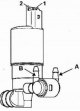
On some car models, a double washer pump is installed (windshield and rear window). The water supply to the washer nozzles depends on the power supply to the pump outputs. When +12V power is applied to the terminal "2"...
On some car models, a double washer pump is installed (windshield and rear window). The water supply to the washer nozzles depends on the power supply to the pump outputs. When +12V power is applied to the terminal "2"...

Rear window heating
The heated rear window is switched on by a switch located on the instrument panel. The current consumed by the heater is large enough, so after defrosting the rear window, turn off the heater. The grid of conductive...
The heated rear window is switched on by a switch located on the instrument panel. The current consumed by the heater is large enough, so after defrosting the rear window, turn off the heater. The grid of conductive...
Instrument cluster and its connectors
Depending on the equipment level, the instrument cluster includes the following: electronic speedometer; tachometer; fuel gauge in the tank; coolant temperature gauge; various control lamps; automatic transmission...
Depending on the equipment level, the instrument cluster includes the following: electronic speedometer; tachometer; fuel gauge in the tank; coolant temperature gauge; various control lamps; automatic transmission...

Center display operation
1. Indicator "low oil level. This indicator appears on the screen for about 30 seconds after the engine starts. If the oil pressure is OK, the message looks like il ok. If the ADAC or RESET button is pressed during the...
1. Indicator "low oil level. This indicator appears on the screen for about 30 seconds after the engine starts. If the oil pressure is OK, the message looks like il ok. If the ADAC or RESET button is pressed during the...

Outdoor temperature sensor
Figure 8.55. Outside temperature sensor in the rearview mirror The outside temperature sensor is located in the outside rearview mirror on the passenger side (Figure 8.55). Figure 8.56. Removing the exterior mirror...
Figure 8.55. Outside temperature sensor in the rearview mirror The outside temperature sensor is located in the outside rearview mirror on the passenger side (Figure 8.55). Figure 8.56. Removing the exterior mirror...

Pressure and oil level sensor
Oil pressure sensor Figure 8.57. Emergency oil pressure drop sensor The sensor is screwed into the cylinder block behind the oil filter (Figure 8.57). To remove the sensor, disconnect the connector from it and unscrew...
Oil pressure sensor Figure 8.57. Emergency oil pressure drop sensor The sensor is screwed into the cylinder block behind the oil filter (Figure 8.57). To remove the sensor, disconnect the connector from it and unscrew...

Fuel level sensor
Connector (from the pump side) Terminal Description A1 "Earth" fuel level sensor A2 Not used IN 1 Fuel level sensor signal AT 2 Not used C1 Fuel pump power (+) C2 "Earth" fuel pump (-) Check: Measure the resistance...
Connector (from the pump side) Terminal Description A1 "Earth" fuel level sensor A2 Not used IN 1 Fuel level sensor signal AT 2 Not used C1 Fuel pump power (+) C2 "Earth" fuel pump (-) Check: Measure the resistance...

Outside air temperature sensor
To replace the sensor, you do not need to remove the mirror, just remove the housing. Release the sensor from the clip and cut the wire (a few centimeters long). When installing a new sensor, solder the wires. Sensor...
To replace the sensor, you do not need to remove the mirror, just remove the housing. Release the sensor from the clip and cut the wire (a few centimeters long). When installing a new sensor, solder the wires. Sensor...
Sound signal — removal and installation
The horn is installed on the left under the front bumper under the headlight. Removing disconnect the wire from the negative terminal of the battery; remove the left front wheel and mudguard; disconnect the connector...
The horn is installed on the left under the front bumper under the headlight. Removing disconnect the wire from the negative terminal of the battery; remove the left front wheel and mudguard; disconnect the connector...

Immobilizer — description, removal and installation
General information Secret access codes are no longer used (those. the number is not stamped on the key, the car does not have a plate with codes). They have been replaced by repair codes reserved for this vehicle. When...
General information Secret access codes are no longer used (those. the number is not stamped on the key, the car does not have a plate with codes). They have been replaced by repair codes reserved for this vehicle. When...

Immobilizer control unit — removal and installation
The immobilizer control unit is installed on the side of the front panel (from the driver's side). The immobilizer control unit consists of several computers and can be installed in two versions: basic N2 and extended...
The immobilizer control unit is installed on the side of the front panel (from the driver's side). The immobilizer control unit consists of several computers and can be installed in two versions: basic N2 and extended...

Cigarette lighter — removal and installation
Removing disconnect the wire from the negative terminal of the battery; remove the center console (see section « Body »); disconnect the connector from the cigarette lighter; remove the heating element from the...
Removing disconnect the wire from the negative terminal of the battery; remove the center console (see section « Body »); disconnect the connector from the cigarette lighter; remove the heating element from the...

Audio system and speakers — removal and installation
Car-mounted car radios have standard DIN connectors. To remove the car radio, special grips are used. Removing disconnect the negative cable from the battery; Figure 8.63. Removing the car radio with grips insert the...
Car-mounted car radios have standard DIN connectors. To remove the car radio, special grips are used. Removing disconnect the negative cable from the battery; Figure 8.63. Removing the car radio with grips insert the...
Airbags — general information
All work on the airbag units and the belt pretensioner must be carried out by qualified personnel with sufficient experience. When working under the vehicle, do not hit the vehicle components without first locking the...
All work on the airbag units and the belt pretensioner must be carried out by qualified personnel with sufficient experience. When working under the vehicle, do not hit the vehicle components without first locking the...

Replacing the Airbag Module
Removing Note. Before removing the airbag, lock the SRS control unit using a diagnostic tester. Note. At undermining of a pillow as a result of failure replace a steering wheel. Check system performance. disconnect the...
Removing Note. Before removing the airbag, lock the SRS control unit using a diagnostic tester. Note. At undermining of a pillow as a result of failure replace a steering wheel. Check system performance. disconnect the...

SRC security unit — removal and installation
Withdrawal: Note. The SRS control unit is located on the center console. Before removing the control unit, lock it with a diagnostic tester. Use only NXR or CUP testers. Disconnect from the central console a cover of...
Withdrawal: Note. The SRS control unit is located on the center console. Before removing the control unit, lock it with a diagnostic tester. Use only NXR or CUP testers. Disconnect from the central console a cover of...
How to find an electrical problem
To determine the faults in the book are electrical circuits of the main circuits of consumers of electricity. The electrical circuit mainly consists of switches, relays, electric motors, actuators, fuses, electric lamps...
To determine the faults in the book are electrical circuits of the main circuits of consumers of electricity. The electrical circuit mainly consists of switches, relays, electric motors, actuators, fuses, electric lamps...
This section is available on: russian, bulgarian, belarusian, ukrainian, serbian, croatian, romanian, polish, slovak, hungarian
Other sections on other Renault models
➽ Electrical equipment: Equipment and devices Renault Duster 1 (2009-2017)
➽ Electrical equipment: Equipment and devices Renault Fluence 1 (2009-2020, petrol)
➽ Electrical equipment: Equipment and devices Renault Kangoo 1 (1997-2007)
➽ Electrical equipment: Equipment and devices Renault Laguna 2 (2001-2007)
➽ Electrical equipment: Equipment and devices Renault Logan 1 (2004-2012, petrol)
➽ Electrical equipment: Equipment and devices Renault Megan 2 (2002-2009, petrol)
➽ Electrical equipment: Equipment and devices Renault Scenic 1 (1996-2003)
➽ Electrical equipment: Equipment and devices Renault 19 (1988-1996)
Link to this section in different formats
TEXTHTMLBB Code
- General information
- User manual
- Maintenance
- Power unit
- Engine repair
- Cooling system
- Fuel system
- Exhaust system
- Ignition system
- Transmission
- Clutch
- Mechanical gearbox
- Automatic gearbox
- Drive shafts
- Chassis, running gear
- Front suspension
- Rear suspension
- Steering
- Brake system
- Body and interior
- Exterior (external elements)
- Interior (internal elements)
- Doors, locks and windows
- Heating and ventilation
- Electrical equipment
- Equipment and devices
- Headlights and lighting
- Power devices
- Electrical circuits
- General information
- User manual
- Car care
- Maintenance
- Power unit
- Engine repair
- Cooling and lubrication system
- Supply system
- Exhaust system
- Ignition system
- Transmission
- Clutch
- Mechanical gearbox
- Automatic gearbox
- Drive shafts
- Chassis, running gear
- Car suspension
- Steering
- Brake system
- Body and interior
- Exterior (external elements)
- Interior (internal elements)
- Doors, locks and windows
- Restoration and repair
- Electrical equipment
- Equipment and devices
- Headlights and lighting
- Power devices
- Heating and ventilation
- Electrical circuits
RenaultBook.ru © 2018–2024 | Mobile version | News and articles | Sitemap: EN BG BY UA RS HR RO PL SK HU | Administration | Site search | Bookmark
Duster 1 (2009-2017) | Fluence 1 (2009-2020, petrol) | Kangoo 1 (1997-2007) | Laguna 2 (2001-2007) | Logan 1 (2004-2012, petrol) | Logan 2 (2012-2020) | Megane 1 (1995-2002) | Megan 2 (2002-2009, petrol) | Scenic 1 (1996-2003) | Symbol 1 (1999-2008, petrol) | Symbol 2 (2008-2013, petrol) | Renault 19 (1988-1996) | Espace I and II (1984-1996) | Espace III (1996-2002) |