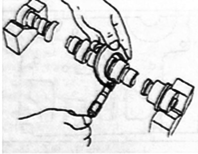
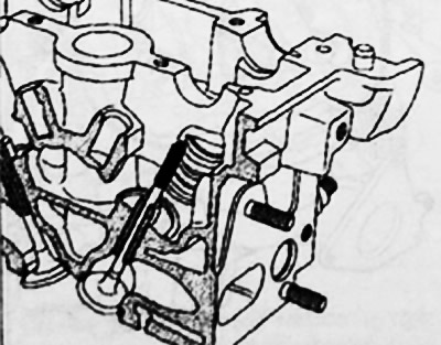
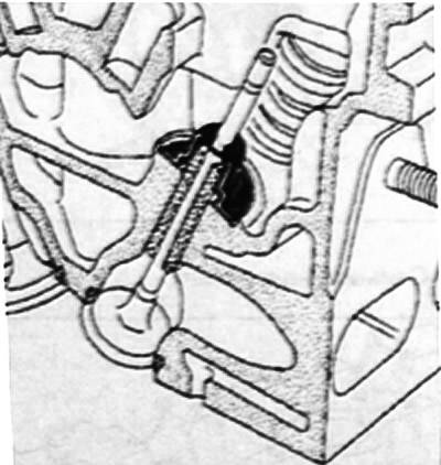
Removing valve springs
To properly compress the valve springs, the tool plunger must be centered (Mot. 1502) along the valve stem.
The plate of the valve spring must be included in the bore of the pressure sleeve of the device (Mot. 1502).
Remove:
- crackers;
- valve spring plates
- valve springs
- valves;
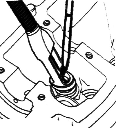
- valve stem seals with pliers (Mot. 1335).
Checking the height of the cylinder head
Measure the height of the cylinder head.
The height of the cylinder head is 137 mm.
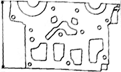
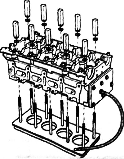
Check of tightness of a head of the block of cylinders
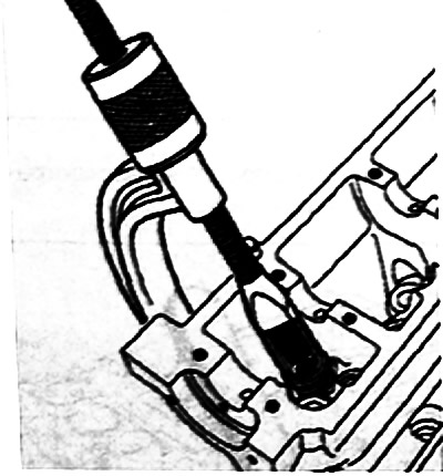
Check the cylinder head for cracks using a special tool.
Measure the height of the cams.
Jaw height:
- inlet: 40.661±0.03 mm;
- exhaust: 40.038±0.03 mm.
Checking the diameters of the bearing journals and the holes of the camshaft bearings
Measure the diameter of the camshafts.
Camshaft journal diameter:
- necks No. 1, 2, 3, 4, 5 - 24.979-25.000 mm;
- neck No. 6 - 27.979-28.000 mm.
Measure the diameter of each hole in the camshaft bearings.
Camshaft bearing bore diameter:
- necks N91, 2, 3, 4, 5 - 25.040-25.061 mm;
- neck No. 6 - 28.040-28.061 mm.
Checking the axial movement of the camshafts
Install the camshafts, making sure they are in the correct position, and the cylinder head cover.
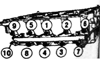
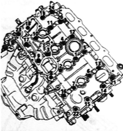
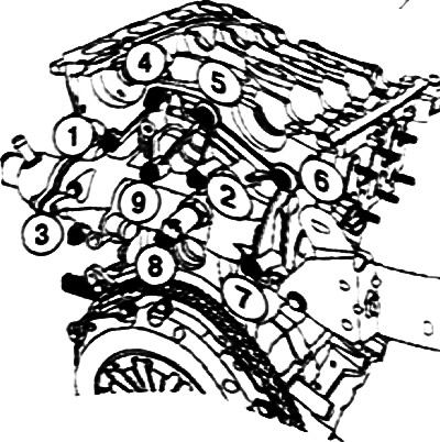
Tighten in the order shown in the figure to the required torque:
- cylinder head bolts 13-20-22-23 (8 Nm);
- cylinder head cover bolts from 1-12, from 14-19 and 21-24 (15 Nm).
Loosen the cylinder head cover bolts 13-20-22-23.
Torque tighten the cylinder head cover bolts 13-20-22-23 in the order shown (15 Nm).
Fasten the magnetic strut to the cylinder head using the mounting plate of the tool (Mot. 588), tightening the wasps with the oil separator mounting bolts and spacers having the following dimensions:
- outer diameter 18 mm;
- bolt hole diameter 89 mm, height 15 mm.
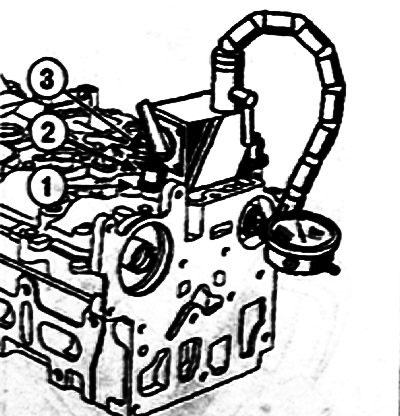
Install the magnetic rack on the cylinder head: 1 - mounting plate; 2 - spacer bushings; 3 - bolts
Check the axial movement, which should be between 0.080-0.178 mm.
Remove the cylinder head cover and camshafts.
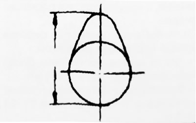
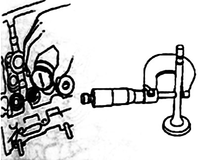
Checking valves
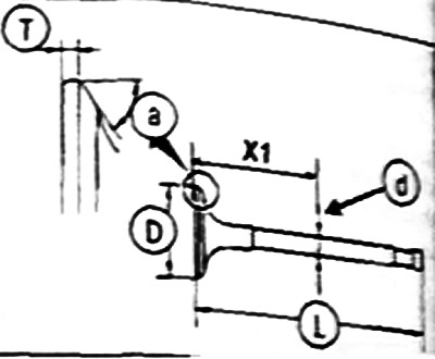
The diameter D of the valve stem is measured at distance X1.
Inlet valves X1: = 75 mm, J = 0.35 mm, D = 5.470-5.485 mm.
Exhaust valves X1: = 77 mm, J = 0.35 mm, D = 5.456-5.471 mm.
Valve head diameter D:
- inlet valves - 32.7±0.12 mm
- exhaust valves - 27.96±0.12 mm.
Valve length L:
- intake valves - 109.32;
- exhaust valves - 107.64 mm.
Chamfer Angle A:
- inlet and outlet valves - 45-45-45°
Head thickness T:
- intake valves - 1.15 mm;
- exhaust valves - 1.27 mm.
Valve travel:
- intake valves - 9.221 mm;
- exhaust valves - 8.075 mm.
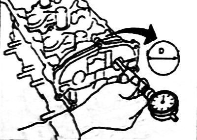
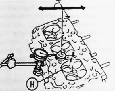
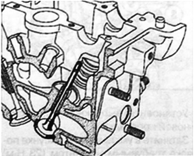
Checking clearance between valve stems and valve guides.
There are two ways to check the clearance between the stems and the valve guide
First method: Raise the valve head 25 mm, then measure the movement of the valve in the direction of the arrows at a 90°angle to the camshaft axis with the indicator. Half of the value obtained is equal to the value of the gap between the stem and the valve guide.
The second way. Measure the valve stem diameter and guide bushing inside diameter.
The clearance between the valve guide and the valve stem is calculated by subtracting the two measured diameters.
Rated Clearance:
- for intake valves - 0.015-0.046 mm;
- for exhaust valves - 0.029-0.062 mm.
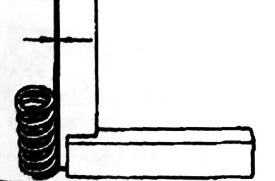
Checking valve springs
Check the deflection of the spring from the vertical, which should not exceed 1.2 mm.
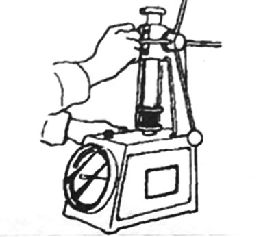
Check spring calibration. The length of the springs under load.
- under a load of 18-20 N, the length of the spring is 34.50 mm;
- under a load of 56.3-81.7 N, the length of the spring is 24.50 mm;
- free spring length 41.30 mm.
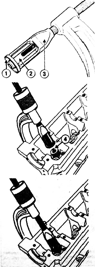
Cylinder head assembly
Insert the valve into the block head.
Put on the tip of the tool (Mot. 1511) on the valve stem (the inner diameter of the tip must be equal to the diameter of the rod).
Keep the valve pressed against the seat.
Install the oil seal (not oiled) on the tip.
Slide the baffle cap until it transitions to a frost tip.
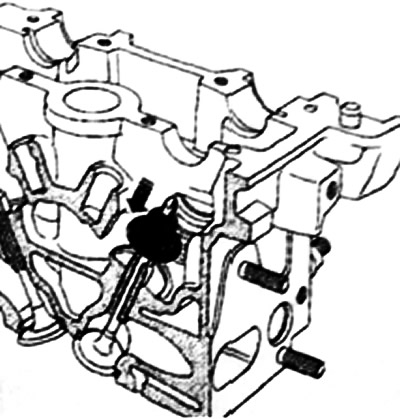
Remove the tip.
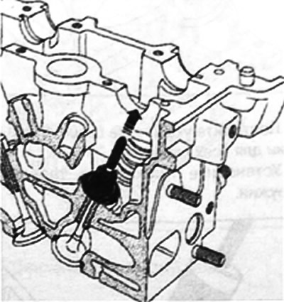
Install the mandrel on the oil seal.
Note. The inner diameter of the neck mandrel is the same as the diameter of the top of the valves. Besides. the lower part of the mandrel should partially rest against the oil cap, which serves as the valve spring washer.
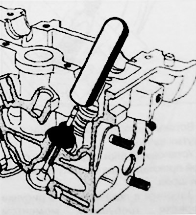
Press on the slinger cap by tapping the top of the mandrel with the palm of your hand until the slinger cap contacts the headstock of the cylinder block.
Repeat the above steps for all valves.
Install springs and spring plates.
Insert crackers with curved tongs.
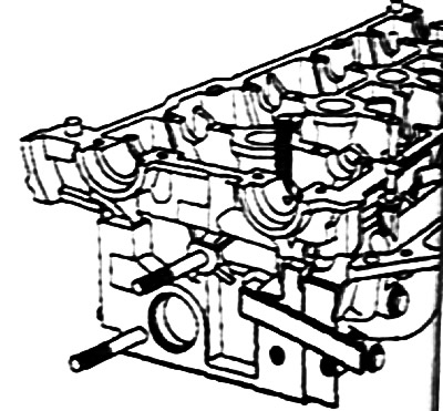
Install the thermostat block with a new gasket on the cylinder head.
Tighten in the order shown in the figure to the required torque (10 Nm) thermostat block bolts on the cylinder head.
 |  |
Install the intake manifold with a new gasket.
Tighten in the front end shown in the figure to the required torque (23 Nm) exhaust manifold nuts.
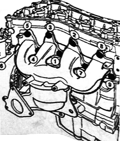
Install the exhaust manifold heat shield. Torque tighten (21 Nm) exhaust manifold heat shield bolts.
Attention! Make sure the exhaust manifold heat shield is securely fixed between the oxygen sensor and the manifold to avoid overheating, which can lead to damage. upstream oxygen sensor wiring).
Torque tighten (4.5 Nm) oxygen sensor using tool (Wot. 1495). Install the inner timing case spacer.
Install the injector body shims with a new gasket.
Install the oxygen sensor. Align the lining of the injector bodies with the cylinder head (from the timing drive).
Align the mating planes of the lining of the injector bodies with respect to the cylinder head.
Tighten in order to the correct torque (21 Nm) bolts for fastening the gasket of the injector housings.