



Contents: Setting the valve timing 🠛 Belt tension 🠛 Checking the timing belt tension 🠛 Checking the valve timing 🠛
The second procedure is used to replace all components that require the removal of one or both camshaft sprockets.
During this operation, be sure to replace the camshaft mounting nuts.
Setting the valve timing
Caution! Be sure to degrease the nose and the hole of the toothed pulley of the crankshaft. The bearing surfaces of the pulley of the crankshaft, as well as the ends of the camshafts (from the timing drive side) and the holes of the toothed pulleys of the camshafts. to avoid slipping of the toothed belt between the toothed pulley of the crankshaft and the pulleys of the camshafts. which can lead to engine failure.
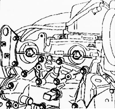
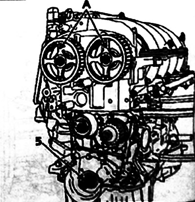
Position the camshaft holes as shown in the figure below, tightening the two old camshaft sprocket nuts onto the camshaft end studs accordingly.
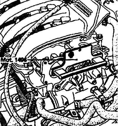
Fix the Mot. 1496 tool to the ends of the camshafts.
Install the camshaft timing pulleys, first tightening the new nuts (do not tighten the nuts completely, the gap between the nut and the toothed pulley should be 0.5-1 mm).
Make sure the crankshaft is securely locked with the top dead center lock (groove 5 of the crankshaft must be directed upwards).
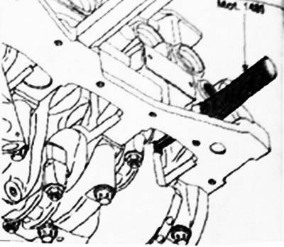
When replacing the timing drive roller, be sure to replace the timing drive tensioner and idler rollers.
 |
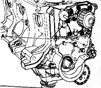 |
Make sure that the roller protrusion fits properly into the groove A.
Place the RENAULT emblem engraved on the spokes of the toothed camshaft pulleys vertically up A, slide the timing belt over the camshaft pulleys, then install the camshaft toothed pulley retainer Mot. 1490 (use the valve timing cover sprinkles to secure the Mot. 1490 attachment).
 |
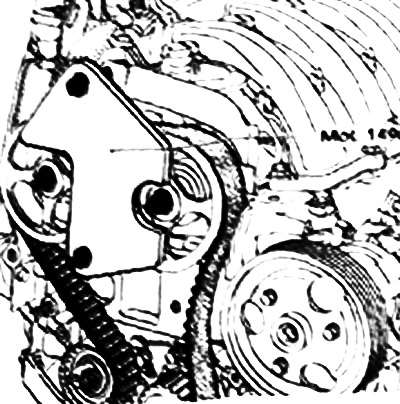 |
Install the idler pulley by tightening the splinter bolt using tool Mot. 1368 to a torque of 45 mm.
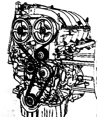
Install the crankshaft pulley after tightening the bolt (do not tighten the bolt completely, the gap between the bolt and the pulley should be 2-3 mm).
Belt tension
Make sure that the gap between the nuts and the camshaft toothed pulleys has not changed and is 0.5-1 mm.
Move the movable pointer (A1) of the tension roller by 7-6 mm in relation to the fixed pointer 7 using a 6 mm Allen key (hole B).
Note: Position A corresponds to the initial position of the movable pointer.
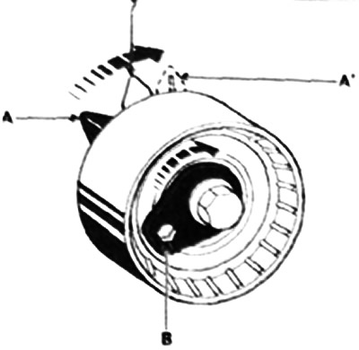
Pre-tighten the tension roller axle splint nut to 7 Nm.
Remove the camshaft timing pulley locking tool Met. 1490.
Rotate the front part of the timing mechanism six turns by the toothed pulley of the exhaust camshaft using tool Mot. 799-01.
Loosen the tension roller axle nut no more than one turn while holding the roller with a 6 mm Allen key.
Align the movable pointer A with the fixed pointer 7 and finally tighten the nut to a torque of 27 Nm.
Remove the crankshaft pulley to allow installation of the lower timing belt cover (without mounting bolts), then reinstall the crankshaft pulley.
Note: The crankshaft pulley bolt is reusable if the length to the head does not exceed 49.1 mm (otherwise replace the bolt).
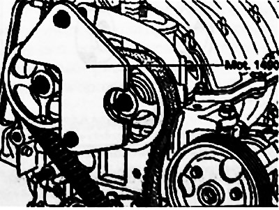
But lubricate the new bolt with engine oil. On the contrary, the reused bolt must be lubricated with engine oil.
Fit the camshaft timing pulley locking tool Mot. 1490, using tool Mot. 799-01 if necessary.
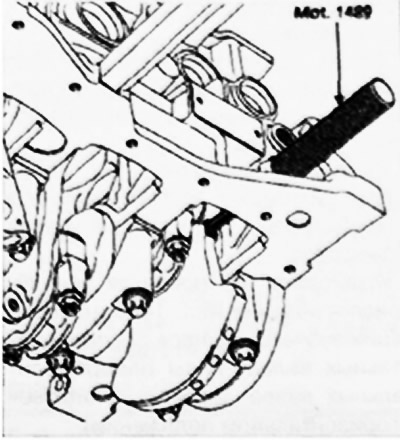
Make sure the crankshaft is securely locked with locking tool Mot. 1489.
Tighten the crankshaft pulley mounting bolt to 2 Nm, then turn it further by 135°±15° (in this case the crankshaft must be locked with the top dead center lock).
Tighten the exhaust camshaft sprocket nut to 30 Nm, then turn it an additional 84°.
Remove tool Mot. 1496 for locking the camshafts, tool Mot. 1490 for locking the camshaft sprockets and top dead centre lock Mot. 1489.
Checking the timing belt tension
Turn the crankshaft two turns clockwise (if you look from the timing drive side), before completing the rotation, screw the Mot. 1489 lock into the cylinder block and slowly, without jerking, move the crankshaft until it rests on the lock.
Remove the top dead center lock.
Make sure the tension roller pointers are aligned, otherwise repeat the tensioning procedure. Loosen the tension roller nut no more than one turn while holding the roller with a 6 mm Allen key.
Align the movable pointer with the fixed pointer and tighten the nut to 2.7 Nm.
Checking the valve timing
When checking the valve timing, make sure that the tension roller indicators are in the correct position.
Screw the Mot. 1489 locking tool into the cylinder block, then turn the crankshaft until it rests against the locking tool.
Install (without any effort) mot 1498 tool for locking camshaft sprockets (the camshaft grooves must be in a horizontal position).
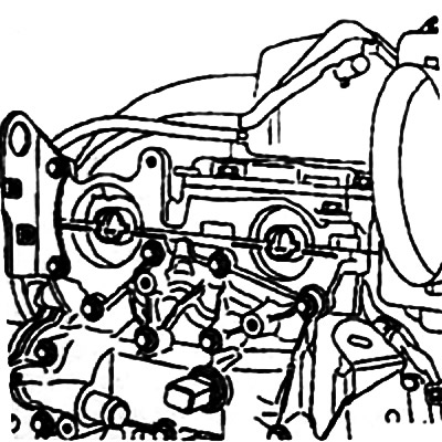
If the device cannot be installed, re-set the valve timing and adjust the timing belt tension.