



Setting the valve timing
Caution! Be sure to degrease the end of the crankshaft, the bore of the crankshaft toothed pulley and the bearing surfaces of the crankshaft toothed pulley. to avoid slipping of the toothed belt on the crankshaft toothed pulley, which may lead to engine failure.
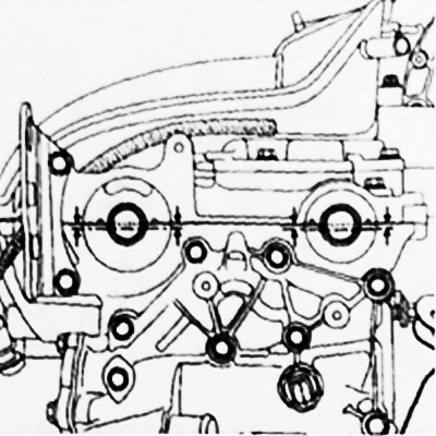
Position the camshaft grooves using tool Mot. 799-01 as shown in the figure.
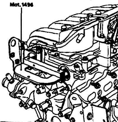
Fix tool Mot. 1496 to the ends of the camshafts.
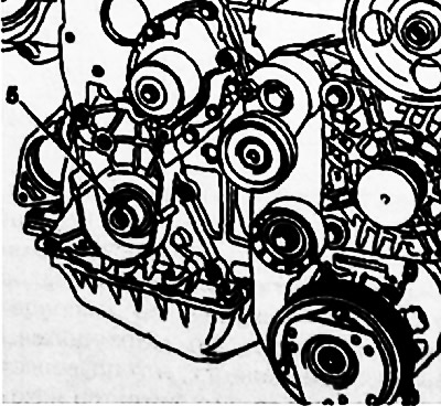
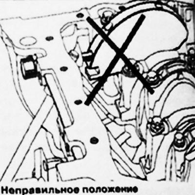
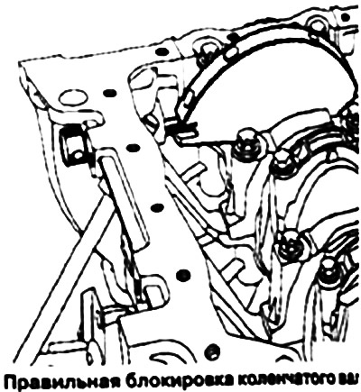
Make sure the crankshaft is locked at top dead center and the locking pin is not in the balance hole (groove 5 of the crankshaft must be directed upwards).
 |
 |
Make sure the intake camshaft phase adjuster ring gear is securely locked (the crown should not rotate either left or right).
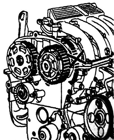
When replacing the timing belt, be sure to replace the timing belt tensioner and idler rollers.
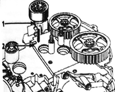
Make sure that the protrusion 1 of the tension roller fits correctly into the groove 2,
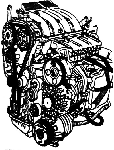
Install:
- timing belt;
- idler pulley 3, tightening the mounting bolt to a torque of 45 Nm;
- crankshaft pulley, having first tightened the bolt (do not tighten the bolt completely, the gap between the bolt and the pulley should be 2-8 mm).
Note: The crankshaft pulley splinter bolt is reusable if the length to the head does not exceed 49.1 mm (otherwise, replace the bolt).
Do not apply engine oil to a new bolt. Instead, be sure to apply engine oil to the threads and underside of the head of a reused bolt.
Note: But rotate the tension roller counterclockwise.
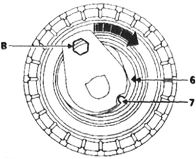
Align marks 6 and 7 on the tension roller using a 6mm Allen key inserted into hole B.
Pre-tighten the tension roller axle mounting nut to a torque of 0.7 Nm.
Tighten the crankshaft pulley mounting bolt to 2 Nm (in this case the top dead center lock Mot. 1054 must be in the corresponding hole in the crankshaft).
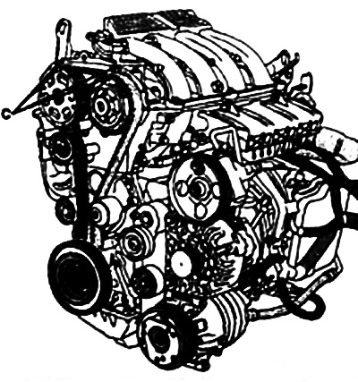
Apply marks C to the toothed ring of the inlet camshaft phase adjuster and to the toothed pulley of the exhaust camshaft relative to the camshaft bearing cap.
Remove tool Mot. 1496 for locking camshafts and top dead centre lock Mot. 1054.
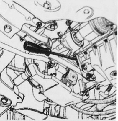
Tighten the crankshaft pulley mounting bolt to an angle of 115°±15° while locking the flywheel with a strong screwdriver.
Checking the timing belt tension
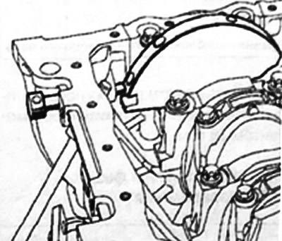
Turn the crankshaft two revolutions clockwise (if you look from the timing drive side). Before the shaft has finished turning two revolutions (i.e. half a tooth before the previously applied marks are aligned), insert the top dead center lock (in this case it is located between the balancing hole and the blocking hole), then set the valve timing mechanism to the position corresponding to the valve timing installation).
Remove the top dead center locking tool Mot. 1054.
Make sure the tension roller marks are aligned, otherwise repeat the belt tension adjustment. To do this, loosen the tension roller axle nut more than one turn while holding the roller with a 6 mm Allen wrench.
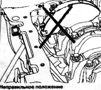 |
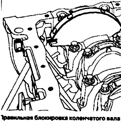 |
Align the tension roller marks and finally tighten the nut to 28 Nm.
Checking the valve timing
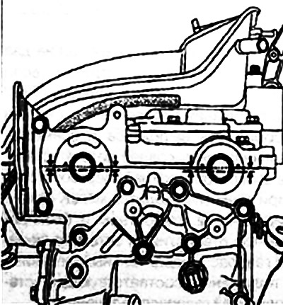
Before checking the valve timing, make sure that the tension roller marks are aligned.
Install the top dead center lock (make sure that the previously applied rolls on the camshaft toothed pulleys are aligned).
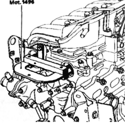
Install (without any effort) mot. 1496 device for fixing camshafts (the camshaft grooves must be in a horizontal position and offset downwards from the axis). If the tool cannot be installed, re-set the valve timing and adjust the timing belt tension.