



Contents: Work performed on the right side of…🠛 Work performed on the left side of…🠛 Engines F4P, K4M, L7X 🠛 Engine F9Q 🠛 Engines of all models 🠛 Features of cars with automatic…🠛 Features of cars with manual…🠛 Engines of all models 🠛 Engine L7X 🠛
Place the vehicle on a two-post lift.
When performing this operation, it is necessary to secure the car on the lift with a brace to prevent the car from becoming unbalanced.
Remove:
- battery;
- front wheels;
- engine sump protection;
- right and left front mudguards and side protective shields.
Drain:
- refrigerant from the air conditioner refrigeration circuit using a charging station;
- coolant by disconnecting the outlet hose from the radiator;
- gearbox and engine oil if necessary.
Work performed on the right side of the vehicle
Remove:
- floating brake caliper and hang it on the suspension spring;
- ABS wheel speed sensor;
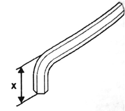
- sprinkler nut for the ball joint pin of the suspension arm (if necessary, use a hex wrench cut to fit the size X=22 mm;
Remove:
- the upper stabilizer bar mount nut and loosen the lower stabilizer bar mount nut;
- two bolts securing the flange! fastening the drive shaft to the intermediate support (f9Q and L7X engines);
- ball joint of the steering rod, using the device T.Av. 476;
- bolts for fastening the telescopic strut to the steering knuckle.
Disconnect the drive shaft, then remove the hub assembly with the drive shaft.
Work performed on the left side of the vehicle
Remove:
- floating brake caliper and hang it on the suspension spring;
- ABS wheel speed sensor;
- suspension arm ball joint pin mounting nut (use a hex key cut to size X=22mm to lock the ball joint if necessary);
- the upper stabilizer bar mount nut and loosen the lower stabilizer bar mount nut;
- ball joint of the steering rod with the help of the device T. Av. 476;
- drive shaft corrugated boot mounting bolts (on cars with manual transmission);
- bolts for fastening the telescopic strut to the steering knuckle.
Disconnect the drive shaft, then remove the hub assembly with the drive shaft.
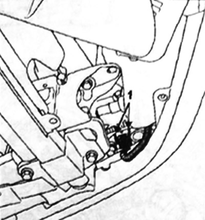
Disconnect the fog lamp connector at point 1.
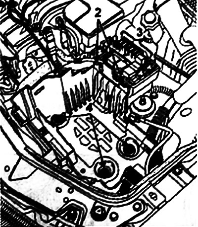
Take it off;
- radiator grille and bumper;
- relay box, pressing the latches 2 and disconnect the fuse holders at points 3;
- shelf under the battery by unscrewing bolts 4.
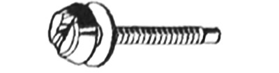
To do this, drill out the three permanent bolts using a 5 mm drill along the bolt axis. Then remove the bolts using the Mot. 1372 tool.
Remove the windshield washer reservoir filler neck.
Disconnect the power steering fluid reservoir and remove its holder.
Disconnect the wire harness from the upper crossmember.
Disconnect the headlight and hood switch connectors (if there is one).
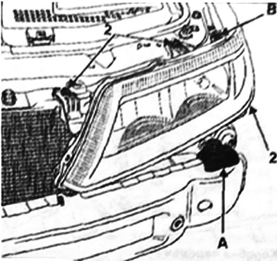
Take it off;
- two upper guides A of the bumper, then detach the holder B of each headlight;
- three bolts for fastening 2 each headlight;
- both headlights.

Remove the upper cross member by removing the hood lock cable.
Remove:
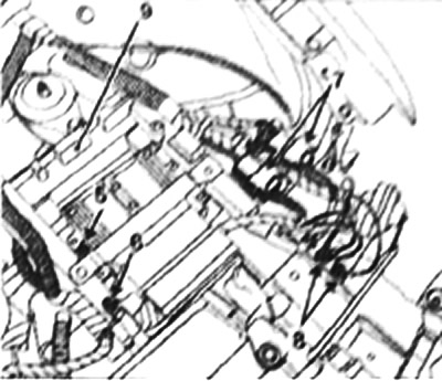
- mounting bolt 5 of the injection system ECU, as well as mounting bolt 6;
- disconnect connectors 7;
- nuts for fastening the "mass" buses 8, then remove the ECU mounting bracket 9;
- intake noise muffler assembly (k4M-F4P engines) or air filter housing (f9Q-L7X engines) and air intake pipe;
- lower radiator mounting bolts and supply hose,
- disconnect the connectors on the cooling system and condenser electric fan group;
- bolts for fastening air conditioning system pipelines to the compressor and receiver-dryer.
Note: Be sure to plug the piping and compressor openings to prevent moisture from entering the system.
Remove the radiator assembly with the condenser.
Engines F4P, K4M, L7X
Disconnect:
- wiring harness and hose from the solenoid valve for purging the absorber;
- fuel line in the area of the upper link of the engine bracket.
Engine F9Q
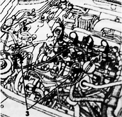
Disconnect the fuel lines at points 3 and the wiring harness from the diesel fuel filter, disconnect them, then set them aside.
Engines of all models
Disconnect:
- brake booster vacuum take-off hose;
- hoses from the expansion tank;
- heater hoses of the thermostat housing, located on the coolant drain line from the cylinder head.
Features of cars with automatic transmission
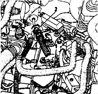
Disconnect:
- ball head 1 cable multifunction switch;
- cable 2 of the multifunction switch, having unlocked the cable sheath stopper.
Note: But move the orange ring during this operation. The ring may break during removal or installation. If this happens, replace the drive cable. The so-called absence of this part does not impair the operation of the system.
Features of cars with manual transmission
Remove:
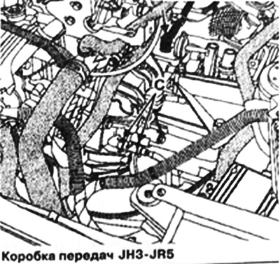
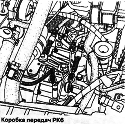
- clutch slave cylinder, disconnecting holders C;
- gear shift drive rod or gear shift and selection cables.
Engines of all models
Remove mounting bolt 3 and loosen bolt 4.
 |
 |
Remove:
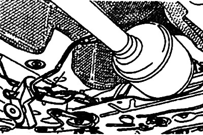
- power steering reservoir return hose, after draining fluid;
- power steering lines on the steering gear;
- oxygen sensor wiring harness, then disconnect the wiring harness (k4M-F4P engines);
- fastenings of the exhaust system inlet pipe, (engines K4M, F4P, F9Q);
- sprinklers of the power steering cooler from the lower cross member;
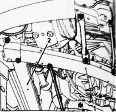
- side members 1 and cross member 2.
The text is available on this website: Renaultbook.ru
Engine L7X
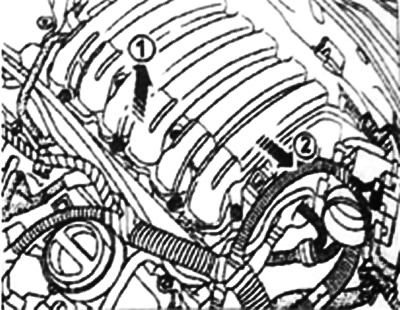
Remove:
- intake manifold mounts
- intake manifold, moving it towards the battery;
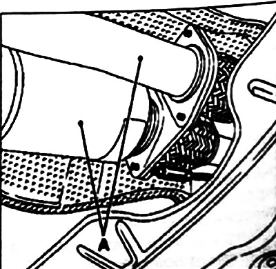
- nuts securing the flange of the catalytic converter and the pre-catalytic converter by inserting the tool through the subframe (use a socket wrench with a long head), then attach the catalytic converters A to the body.
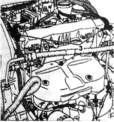
Remove:
- 3 oxygen sensor wiring harnesses;
- nuts for mounting studs 4 of the preliminary catalytic converter.
Remove the sprinkling bolt 5, then remove the pre-catalytic converter.
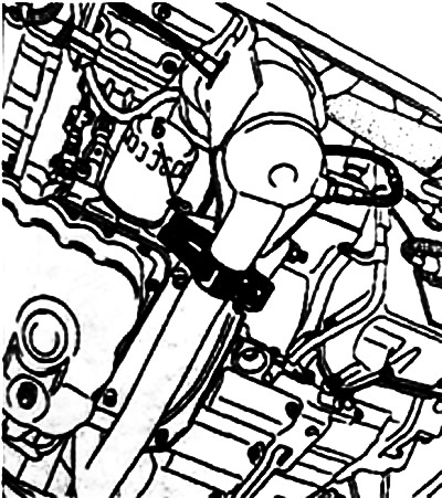
Remove the 6 oxygen sensor wire blocks, the nuts of the studs 7 of the pre-catalytic converter and the brace 8.
Install the workshop crane.
Raise the engine and gearbox assembly using a hoist.
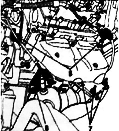
Remove nut 3 and use a bronze drift to knock out the sprinkling pin.
Remove:
- acoustic mass 4;
- traction rod mounting bolts 5, then remove the pendulum suspension support unit - travel limiter.
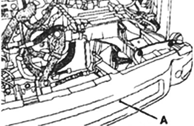
Remove the lower cross member A.
Note: The crossmember is a stiffening element of the engine compartment. Therefore, before any work on the crossmember, be sure to hang the engine.
Using a shop crane, remove the engine assembly with the gearbox.
Attention! Install the lower cross member in place after removing the engine assembly with the gearbox.