
Remove the cover and clutch disc.
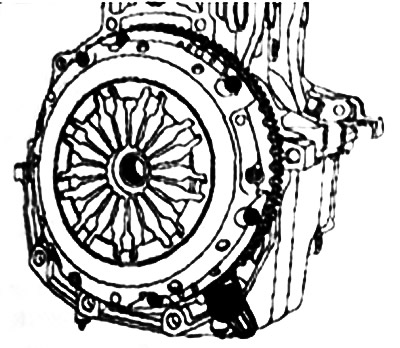
Remove flywheel. Remove the engine tray.
Remove the timing belt tensioner.
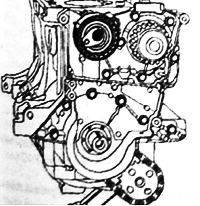
Remove the water pump.
Remove the engine block front cover.
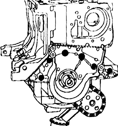
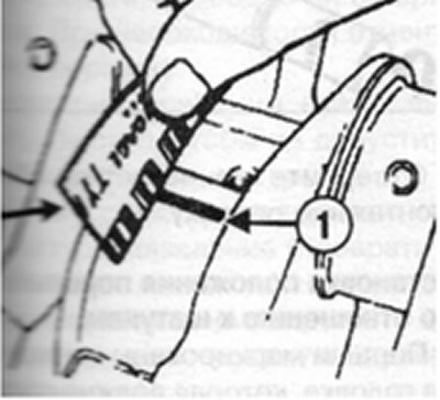
Remove the oil level sensor 1 and the oil softener.
Remove the oil pump and oil pump drive chain.
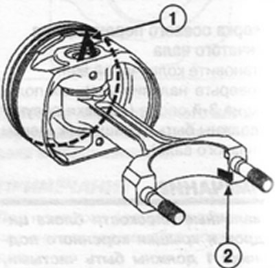
Attention! Do not use a center punch or engraver to mark the cap against the bottom head as this may cause the connecting rod to break. Use an indelible pencil.
Unscrew the connecting rod cap nuts and remove the pistons with connecting rods as an assembly.
Note. Be sure to mark the crown bearing shells with respect to the crankshaft bearings, as different classes of bearings can be installed on the bearings.
Remove the crankshaft bearing caps (bearing caps are numbered from 1 to S).
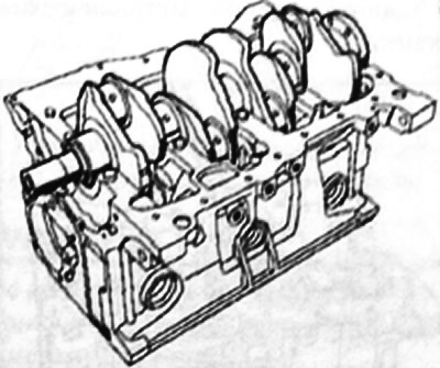
Remove the crankshaft.
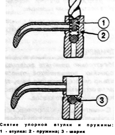
Removing nozzles for cooling piston bottoms
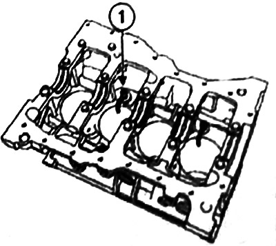
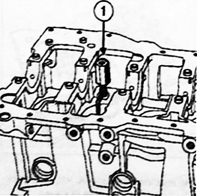
Remove the piston head cooling nozzles 1.
Do not remove the ball so that the chips do not fall into the oil channel.
Drill out the nozzles for cooling the piston heads with a 7 mm drill bit.
Remove the spring retainer and the spring itself.
Remove metal filings with a brush.
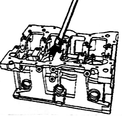
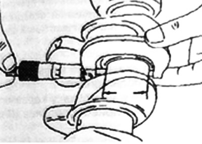
Wrap in nozzle fixture (Mot 1485) or (Mot 1485-01) 1 with a 6mm hex wrench by inserting it into the fixture.
Screw inertial puller 1 (Emb. 880) on adaptation (Mot 1485 or Mot 1485-01).
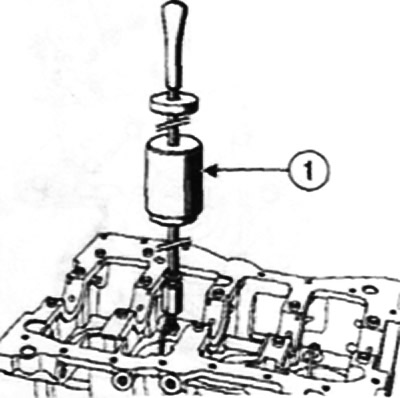
Remove nozzles.
Cleaning the bottom of the engine
Clear:
- engine tray;
- front cover of the engine block;
- crankshaft bearing caps.
Checking the mating plane of the cylinder block
Check with a straightedge and a set of feeler gauges for the flatness of the mating plane of the cylinder block, which should not exceed 0.03 mm.
Checking the diameter of the main bearings of the crankshaft
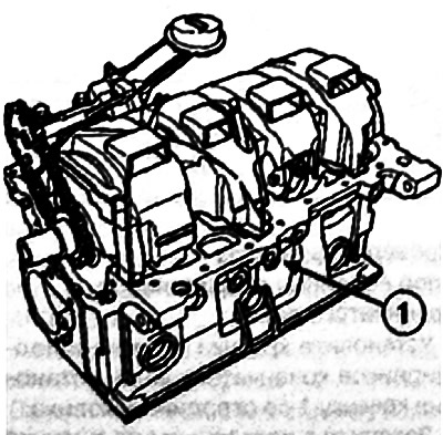
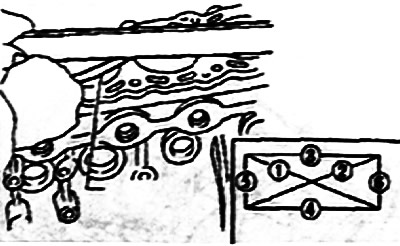
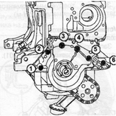
Install the crankshaft main bearing caps by installing cap 1 on the flywheel side.
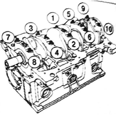
Tighten in the order shown in the figure to the required torque (25 Nm + 47°±5°) and tighten the crankshaft main bearing cap bolts to the required angle.
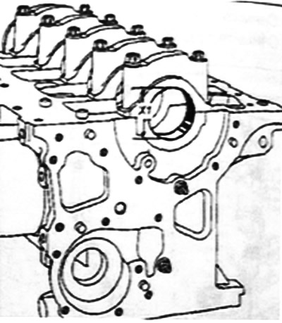
Measure the diameter of the holes of the crankshaft bearings, which should be within X1 = 51.936-51.949 mm.
Remove the crankshaft main bearing caps.
Checking the diameter of the main journals
Check the crown diameter.
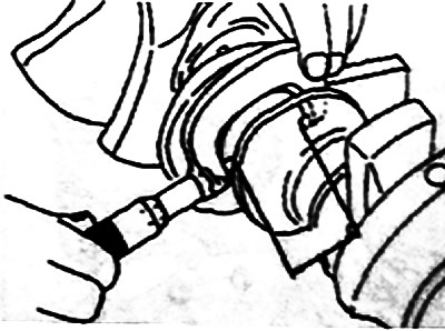
Crown neck diameter should be between 47.990-48.010 mm.
Checking the diameter of the connecting rod journals
Check the diameter of the connecting rod journals.
The diameter of the connecting rod journals should be within 43.960-43.980 mm.
Removing piston pins
Remove the piston rings with piston ring pliers.
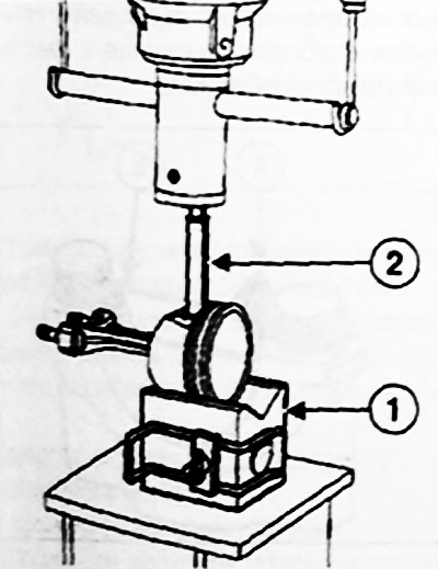
Install the piston assembly with brown-haired on the prism of the fixture (Mot 574-22).
Align the piston pin with the hole for its exit in the prism 1.
Using a press, press out the piston pin with a drift 2 tools (Mot. 574-22).
Checking the clearance between piston rings and piston grooves
With a set of feeler gauges 1, check the clearances with the piston grooves and piston rings.
The clearance for the upper compression ring should be within 0.04-0.08 mm.
The gap for the lower compression ring should be in the range of 0.025-0.07 mm.
The clearance for the oil scraper ring should be in the range of 0.08-0.22 mm.
If the clearances are out of range, replace the piston with piston pin or piston rings.
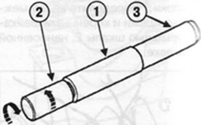
Checking clearances in the piston ring lock
Install the piston ring in the cylinder.
Move the piston ring to the middle of the cylinder with the piston.
Measure the ring gap in the lock with a set of feeler gauges.
Ring gaps:
- for the upper compression ring, the gap should be in the range of 0.15-0.30 mm;
- the gap for the lower compression ring should be in the range of 0.4-0.6 mm;
- the gap for the oil scraper ring should be in the range of 0.2-0.9 mm.
Replace the piston rings if the gaps are out of tolerance, and if the gaps remain out of tolerance with new rings, replace the cylinder block.
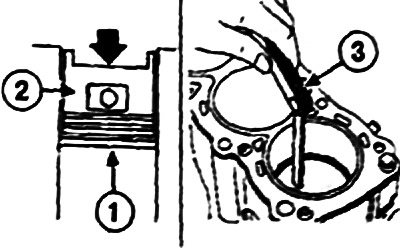
Checking clearances in the piston ring lock: 1 - piston ring; 2 - piston; 3 - probe
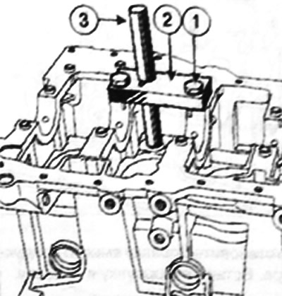
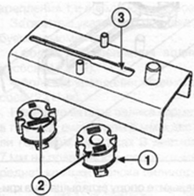
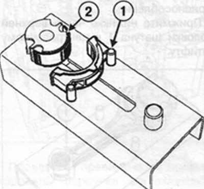
Installation of nozzles for cooling the piston crown
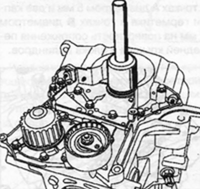
Install the tool plate 2 on the cylinder block (Mot 1494), but tightening the two mounting bolts
Install the jig into the plate (the end of the conductor must enter the hole for the nozzle) to center the plate.
Tighten the two sprinkling bolts 1. Remove the jig 3.
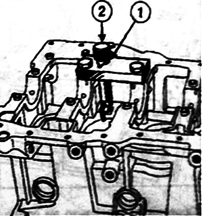
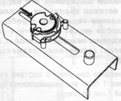
Install the mandrel instead of the conductor. Insert the nozzle into the mandrel,
Attention! When installing the nozzle, its tip should be directed towards the center of the cylinder.
Apply several blows with a hammer on the mandrel until the flange of the mandrel 2 touches the support.
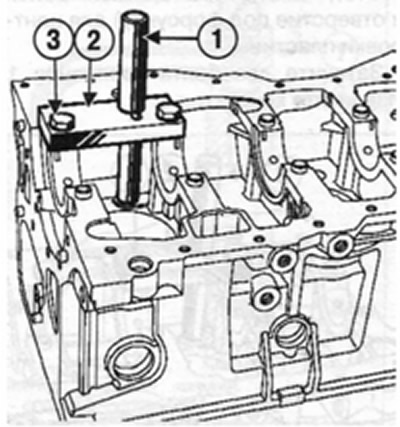
Installation of injectors for cylinders 2 and 4
Install the jig into the plate (the end of the conductor must enter the hole for the nozzle) to center the plate.
Tighten the two fastening bolts 1. Remove the jig 3.
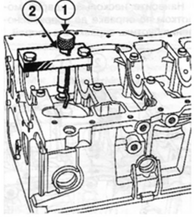
Install the mandrel instead of the conductor. Insert the nozzle into the mandrel.
Attention! When installing the nozzle, its tip should be directed towards the center of the cylinder.
Apply several blows with a hammer on the mandrel until the flange of the mandrel 2 touches the support.
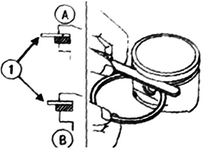
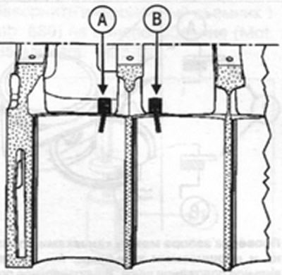
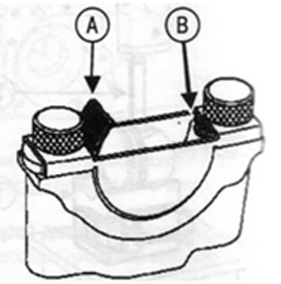
Check that the nozzles for cooling the piston heads are correctly oriented. Mark A corresponds to the injectors of cylinders 2 and 4, and mark B corresponds to the injectors of cylinders 1 and 3.
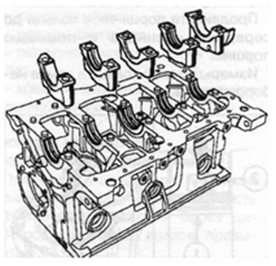
Installation direction of the crankshaft main bearing shells
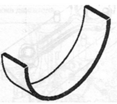
Establish liners with flutes in all beds of the block of cylinders.
Install the grooved shells in the main bearing caps 2 and 4, and the non-grooved shells in the main bearing caps 1, 3 and 5.
Installing the main bearing shells in the bed of the cylinder block
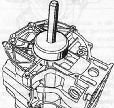
Install the fixture on the block (Mot. 1493-01).
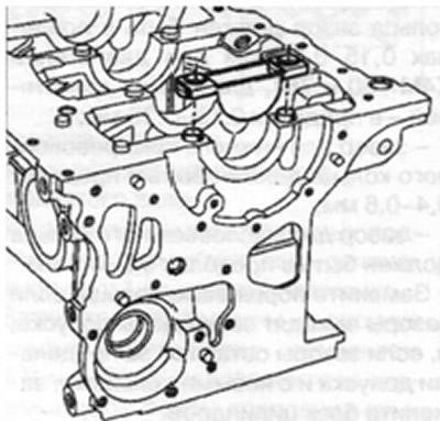
Press the special tool until the liner contacts the tool plate
Installing shells in main bearing caps
Install the tool on the main bearing cap (Mot. 1493-01).
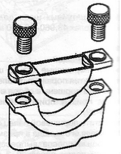
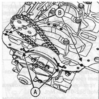
Press at points A and B shown in the figure until the insert is in contact with the fixture plate.
Checking the diametrical clearance with the crankshaft main journals and bearings
Note. When checking the clearance, never turn the crankshaft.
Remove oil residues from the main journals and bearings of the cylinder block.
Install the crankshaft and crankshaft thrust washers on the 3rd support (grooves to the cheeks of the crankshaft).
Cut a few pieces of calibrated wire, lay the wire along the axis of the crankshaft main journals (outside the area of the lubrication holes. Establish covers of radical bearings of a cranked shaft, position a cover 1 from a flywheel. Tighten in order to the correct torque (25 Nm+47°±5°). Turn the crankshaft main bearing cap bolts, crankshaft main bearing caps to the required angle. And flattening the calibrated strip 1, determine the gap between the liners and the main journals using the scale 2 printed on the package.
Set the gap value, which should be 0.027-0.054 mm. Clean the crankshaft and main bearing shells from the remnants of the calibrated wire.
Checking the axial movement of the crankshaft
Attention! The mating surfaces of the cylinder block and main bearing cap 1 must be clean, dry and free of oil (don't touch them with your fingers).
Attention! Applying too much sealant can cause it to be squeezed out when parts are tightened. The ingress of sealant into working fluids can lead to damage to some components and assemblies (engine, radiator, etc.).
Apply two bead of sealant compound 1 (or its equivalent) 1 mm wide per support.

Install the crankshaft main bearing caps with cap 1 on the flywheel side.
Tighten in order to the correct torque (25 Nm + 47°±5°) and tighten the crankshaft main bearing cap bolts to the required angle
Check the axial movement of the crankshaft.
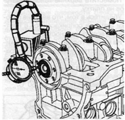
Axial movement with new thrust half rings is 0.045-0.252 mm.
The axial displacement with the thrust half rings operated is 0.045-0.852 mm.
Make sure that the crankshaft rotates freely without binding.
Installing connecting rod bearing shells
The engine is equipped with liners without a mustache.
Inserts are installed with a tool (Mot 1492).
Select the liner holder according to the engine model (engine model is indicated on the bracket).
Install the insert holder into the groove of the support.
Install the connecting rod on the special tool.
Press the bottom of the upper head of the connecting rod 1 to the centering pin.
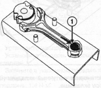
Install insert 1 on the support.
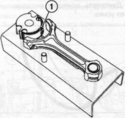
Push the bushing support in the direction shown by the arrow in the figure, it will not go all the way into the crank head of the connecting rod.
Remove the bushing support 1 from the crank head of the connecting rod and repeat the operations with the rest of the connecting rods
Place the connecting rod cap against the tabs on the support 2.
Install the connecting rod bearing on the bearing support.
Push the liner holder in the direction shown by the arrow in the figure until the liner holder is fully seated in the connecting rod cap.
Remove the bushing support from the connecting rod cap and repeat the operations for the rest of the connecting rod caps.
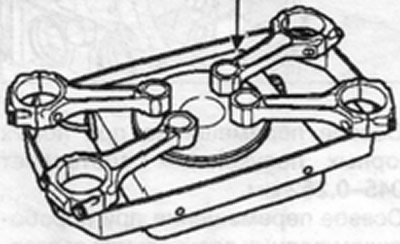
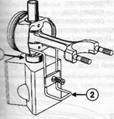
Assembly of connecting rods with pistons
The piston pins are installed with an interference fit in the upper heads of the connecting rods and rotate freely in the piston bosses. use kit (Mot 574-22) and fixture (Mot 574-24).
Visually check:
- condition of connecting rods (twisting and bending);
- the cleanliness of the bearing surfaces of the cover and the crank head of the connecting rod.
Use a 1500W heating plate.
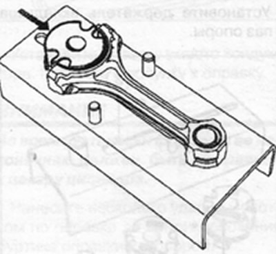
Place the upper connecting rod heads on the tile.
Make sure the upper ends of the connecting rods are in full contact with the tile
Place on each connecting rod head (as temperature indicator) a piece of tin solder at the point indicated by the arrow in the figure, where the melting point is approximately 250°C.
Heat the top ends of the connecting rods until the solder melts.
Piston pin preparation
Check that the piston pins rotate freely in the bosses of the respective new pistons
Use centering mandrel C 13 and mounting mandrel A13 from the kit (Mot. 574-22) for piston pins without collar.
Use centering mandrel C 13 and mounting mandrel A13-01 from the kit (Mot. 574-24) for flanged piston pins.
Install the piston pin on the mounting mandrel 2 and screw the centering mandrel 3 until the assembly is tightened.
Loosen the mounting mandrel a quarter of a turn.
Setting the position of the pistons in relation to the connecting rods.
Pistons are labeled «V» on the head, which should be located on the side of the flywheel.
Position the piston head with the mark «V» up
Direct the locking barb of the connecting rod bearing 2 down.
Piston and connecting rod assembly
Mount the ring 1 B10 on the prism and the piston supported on the ring oriented in the correct position, and fasten all the parts with clamp 2.
Make sure the piston pin bore is aligned with the B10 pin bore.
Lubricate the centering mandrel and piston pin with engine oil.
Insert the piston pin into the assembly and check if it rotates freely. Center the piston if necessary.
The following operations must be carried out quickly to prevent the connecting rod head from cooling.
When the piece of solder reaches its melting point (turn into a drop):
- remove a drop of solder;
- insert the centering mandrel into the piston;
- insert the correctly oriented connecting rod into the piston;
- quickly lower the piston pin until the centering mandrel rests on the bottom of the tool.
Make sure that the piston pin does not protrude from the piston in any position of the connecting rod.
Installation of piston rings
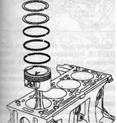
The piston rings are matched to the piston and must move freely in the piston grooves.
Observe the installation direction of the rings (TOP label is directed upwards).
Observe the position of the lock of each ring.
Assembly of the lower part of the engine
Lubricate the upper parts of the cylinders and the connecting rod journals of the crankshaft with engine oil.
Reinstall the pistons and connecting rods with the tool.
Install crankshaft connecting rods Install connecting rod caps Torque tighten (20 Nm + 45°±6°) and tighten the nuts of the studs securing the connecting rod caps to the required angle. Install:
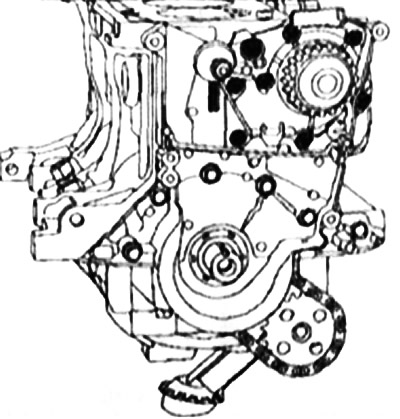
- oil pump drive sprocket;
- oil pump drive chain;
- oil pump Torque tighten (25 Nm) oil pump bolts.
The tightness of the front cover of the engine block is ensured by installing a gasket or applying sealant.
Note. The mating surfaces of the cylinder block and the front cover of the engine block must be clean, dry and free from oil (don't touch them with your fingers). If LOCTITE 518 is selected to seal the engine block front cover, apply with 1mm wide tape as shown.
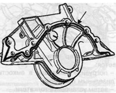
Install the engine block front cover.
Tighten in the order shown in the figure to the required torque (12 Nm) bolts of fastening of a forward cover of the block of the engine.
Install the water pump.
Apply one or two drops of LOCTITE FRENETANCH to the water pump mounting bolts 1 and 4.
Tighten in order to the correct torque:
- M6 bolts for mounting the water pump (11 Nm);
- water pump mounting bolt M8 (22 Nm).
Apply four beads of sealant at points A with a diameter of 5 mm and two drops of sealant at points B with a diameter of 7 mm on the mating surface of the front cover and cylinder block.
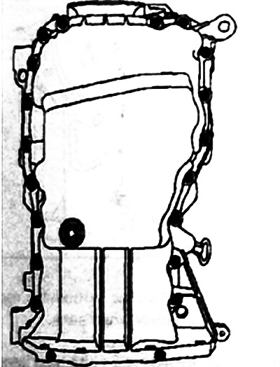
Install an oil softener. Install the pan with a new gasket.
Tighten in order to the required torque: pan bolts: 14 Nm.
Install the oil level sensor.
Torque tighten the oil level sensor (20 Nm).
Install the knock sensor.
Torque tighten the knock sensor (20 Nm),
Install the oil pressure sensor.
Torque tighten the oil pressure switch (32 Nm).
Installation of crankshaft seals
Press in the crankshaft rear oil seal with a mandrel (Mot. 1129-01).
Press in the front crankshaft oil seal with a mandrel (Mot. 1385).
Install the flywheel with new mounting bolts.
Install the flywheel retainer (Mot. 582-01 or Mot. 1677).
Torque tighten (55 Nm) flywheel bolts.
Install:
- clutch disc;
- clutch cover with pressure plate assembly.
Center the driven disc with a mandrel (Emb. 1518).
Torque tighten (0.8 Nm) clutch cover bolts.
Remove the flywheel retainer.