Attention:
It is strictly forbidden to supply compressed air to the engine oil pan.
Damage to the oil pan can also cause various damages to the engine itself due to:
- blocking the oil intake;
- increasing the engine oil level above the maximum mark, which may cause the engine to run away.
1. Remove the cylinder head from the engine.
2. Install the cylinder head on the special support (Mot. 1573).
3. Remove the exhaust manifold (see chapter "Intake and exhaust system").
4. Loosen the bolt (2) of the camshaft sprocket using the timing drive lock (Mot. 799-01).
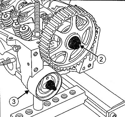
5. Remove the camshaft sprocket.
6. Loosen the fastening nut and remove the tension roller (3).
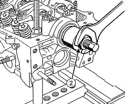
7. Remove the camshaft oil seal from the timing drive side:
- Screw the camshaft oil seal extractor 30 x 42 x 7 (Mot. 1381) (2) into the oil seal.
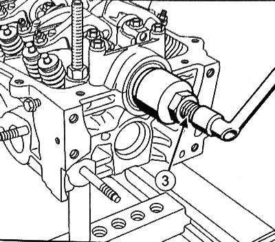
- Tightening the bolt (3) of the camshaft oil seal puller 30 x 42 x 7 (Mot. 1381), remove the oil seal from the cylinder head.
8. Loosen the mounting bolts (4) and remove the rigging eye.
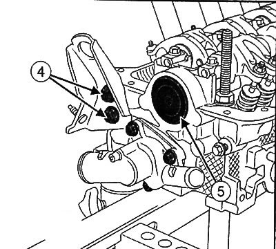
9. Remove the cooling system chamber (see chapter "Cooling system").
10. If equipped, remove the camshaft sealing plug (5).
11. Remove the spark plugs.
12. Loosen the camshaft bearing cap mounting bolts and remove the rocker arm shaft from the cylinder head.
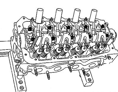
13. Mark the camshaft bearing caps with a marker.
You can find the original at this link [www.RENAULTBOOK.ru]
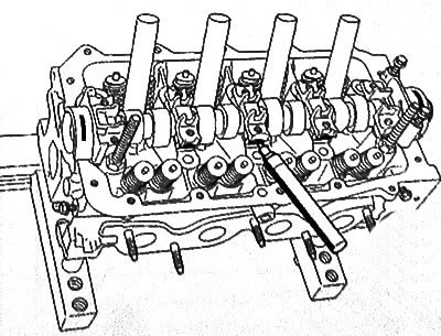
14. Loosen the camshaft bearing cover mounting bolts No.5 (4).
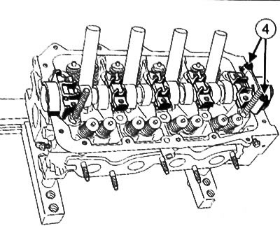
15. Remove the camshaft bearing caps.
16. Remove the camshaft from the cylinder head.
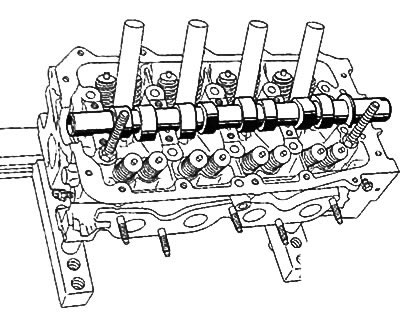
17. Remove the valves from the cylinder head:
- Mark the installation position of each valve with a marker.
Note: The valve springs are compressed using a special tool (Mot. 1502).
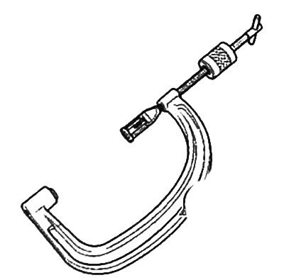
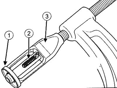
- For correct compression of the valve spring, it is very important that the piston (2) of the tool (Mot. 1502) is centered on the valve stem (4). The valve plate must enter the body (1) of the seat (3) of the valve spring compressor tool (Mot. 1502).
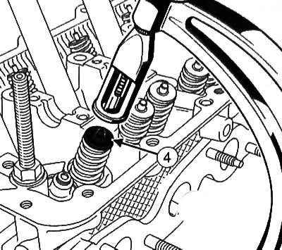
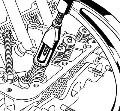
- Use tweezers to remove the crackers (5).
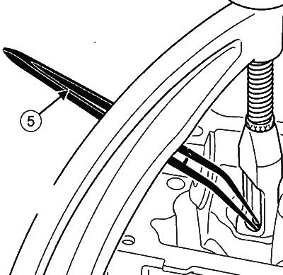
- Remove the valve plate, valve spring and the valve itself.
Note:
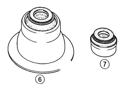
There are two types of valve stem seals:
- oil deflector cap with lower spring retaining washer (6),
- oil deflector cap without lower spring retaining washer (7).
18.Only valve stem seals without lower spring retaining washer:
Note: Before removing the valve stem seal, it is important to mark the dimension (H) of the old valve stem seals on the intake and exhaust sides (the installation size of the inlet and outlet caps may differ).
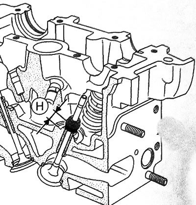
- Install the valve to mark the installation dimension (H) of the old valve stem seal with the lower spring retaining washer using the valve stem seal installation tool (Mot. 1759) or valve stem seal installation kit.
- Install the mandrel (8) of the valve stem seal press tool (Mot. 1759) onto the valve stem seal.
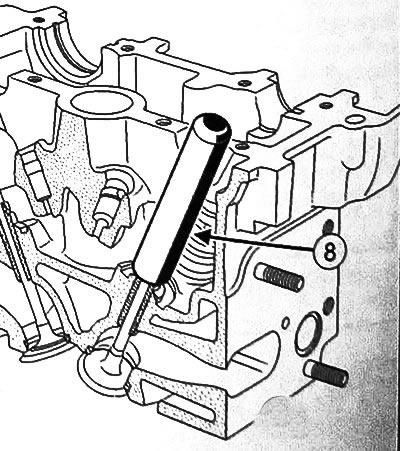
Note: The inside diameter of the mandrel must be identical to the valve diameter so that the bottom of the mandrel covers the metal top section of the valve stem seal.
- Install the guide tube (9) over the mandrel so that the tube touches the cylinder block
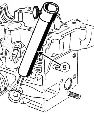
- Insert the sleeve (10) into the guide tube until it contacts the mandrel.
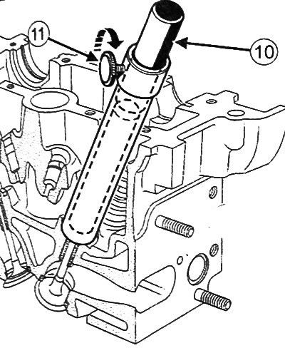
- Secure the sleeve with the fixing screw (11).
- Remove the guide tube and bushing assembly, being careful not to loosen the retaining screw.
- Remove the valve.
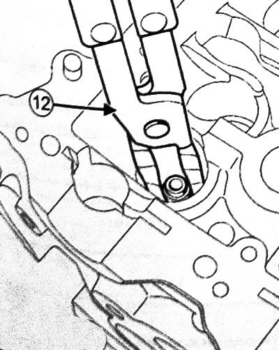
19. Remove the valve stem seals using special pliers (Mot. 1335) (12).