
Attachment drive belts
Replacing Attachment Drive Belts
Attention:
- Wear protective gloves when performing work.
- To avoid damage to the crankshaft pulley, do not start the engine with the attachment drive belts removed.
- Replace the drive belts, crankshaft pulley and crankshaft pulley bolt with new ones after each removal.
1. Place the vehicle on a two post lift.
2. Disconnect the negative battery terminal.
3. Unscrew the fastening bolts and remove the engine protective tray.
4. Remove the front right wheel from the vehicle.
5. Remove the front right fender liner.
Versions with air conditioning and power steering
6. Loosen the fixed roller bolt.
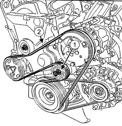
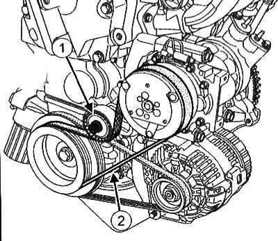
7. With special tool (Mot. 1368) unscrew the bolt (1) tension roller and remove the drive belt (2).
Versions with air conditioning without power steering
8. With special tool (Mot. 1368) unscrew the bolt (1) tension roller and remove the drive belt (2).
Continuation for all versions
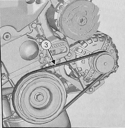
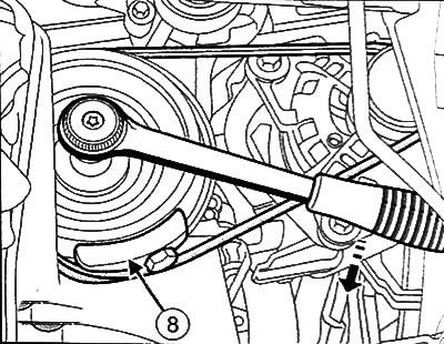
9. Cut the alternator drive belt (3).
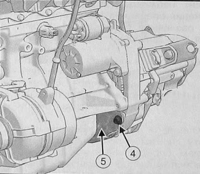
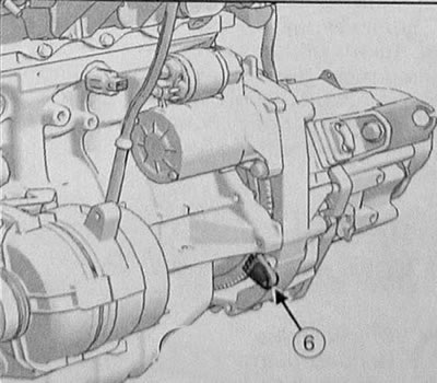
10. Loosen the bolt (4) and remove flywheel guard (5).
11. Install flywheel locking tool (Mot. 582-01) (6).
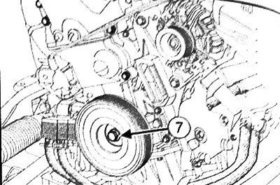
12. Loosen the bolt (7) and remove the attachment drive pulley.
13. Clean the grooves of the new crankshaft pulleys with a brush to remove any deposits.
Caution: Only use a brush with bristles made of plastic or non-corrosive metals (e.g. copper).
Versions with air conditioning and power steering
19. Install a new drive belt according to the diagram shown in the figure.
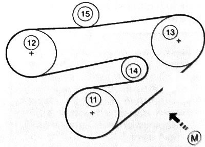
11. Crankshaft. 12. Power steering pump. 13. A/C compressor 14. Tensioner pulley 15. Fixed pulley M. Drive belt tension test point
20.Install the new fixed roller and tighten the retaining bolt.
21. Install a new idler roller and tighten the mounting bolt.
Versions with air conditioning without power steering
22.Install a new drive belt according to the diagram shown in the figure.
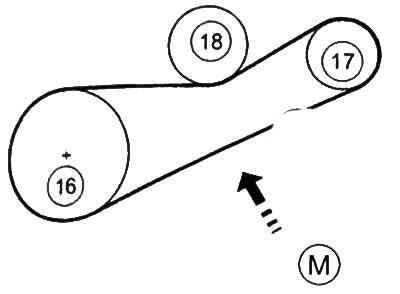
16. Crankshaft. 17. Air conditioning compressor. 18. Tension roller. M. Check point for drive belt tension.
23.Install a new tensioning roller and tighten the retaining bolt.
Continuation for all versions
24.Check and adjust drive belt tension (see related section below).
Note: Drive belt tension value: 219Hz±4Hz.
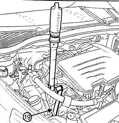
25. Tighten the idler bolt to 44 Nm using the special tool for tightening the eccentric idler bolt (Mot. 1368) (19).
26.Turn the engine crankshaft three turns clockwise (from the drive side of the gas distribution mechanism) for shrinking the attachment drive belt.
27. Check the tension of the natural belt again. If the tension is not correct, repeat the adjustment.
28.Install the attachment drive belt guard.
29. Further installation is carried out in the reverse order of removal.
Checking Attachment Belt Tension
Frequency meter Mot.1715 or frequency indicator Mot. 1715 measure the tension of an attachment drive belt when troubleshooting or replacing a drive belt.
The manufacturer's recommended drive belt tension must be observed as it directly affects the life of the drive system.
Improper drive belt tension can cause noisy operation, power loss, engine stalls or even serious engine damage.
Verification procedure
Note:
- The instruments measure the vibration frequency of the installed drive belt. The oscillation frequency is the physical quantity that allows you to accurately determine the correct tension of the drive belt.
- Measurements should not be made with only one sensor, the second sensor is used as a reference, so it must be located outside the measurement area.
- Both sensors can be used both as a measurement and as a reference.
- Measuring range: 30-520 Hz.
- Accuracy:±1 Hz < 100 Hz and 1% > 100 Hz.
Tool Mot.1505
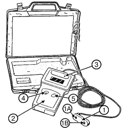
Appliance Mot. 1505:
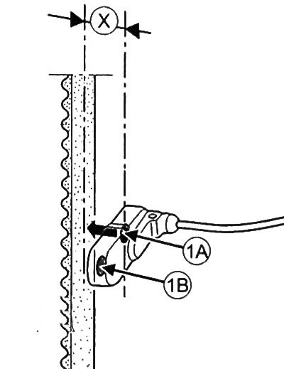
1. Reading head with two sensors (1A and 113). 2. Display block. 3. Calibration frequency generator (512Hz) built-in display unit 4. Power switch. 5. Checking off, to calibrate the equipment.
1. Turn on the device using the switch (4).
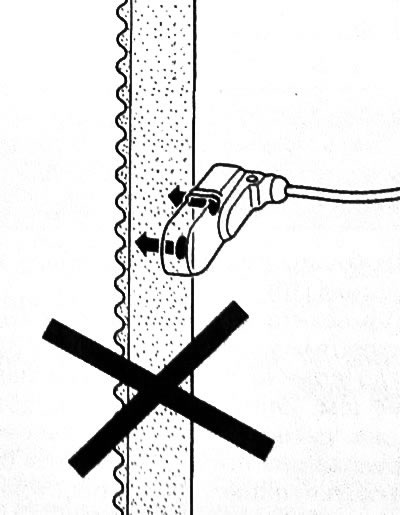
2. Place the read head (1) opposite the section of the drive belt where the measurement is to be taken (see illustration in section "Replacing Attachment Drive Belts" higher). Place the read head (1) on distance (X), which is from 5 to 10 mm from the belt. Measurement can be taken from either side of the drive belt (7 or 8).
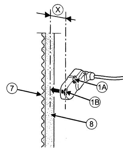
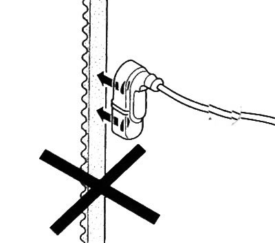
Note: Can be used as a sensor (1A), and the sensor (1B). In this case, while one of the sensors is being used, the second must be outside the measurement zone. Simultaneous frequency measurement with two sensors is not allowed.
3. Using your finger to vibrate the drive belt, measure the frequency of oscillation.
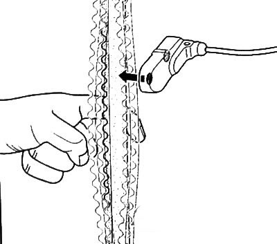
Note: The process of measuring the oscillation frequency is confirmed by the sound signal of the device.
Tool Mot.1715
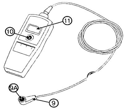
Device Mot.1715:
9. Read head with one sensor (9A). 10. Power switch. 11. Display.
1. Turn on the device using the switch (10).
2. Place the read head (9) opposite the section of the drive belt where the measurement is to be taken (see illustration in section "Replacing Attachment Drive Belts" higher). Place the read head (1) on distance (X), which is from 5 to 10 mm from the belt. Measurement can be taken from either side of the drive belt (12 or 13).

3. Using your finger to vibrate the drive belt, measure the frequency of oscillation.
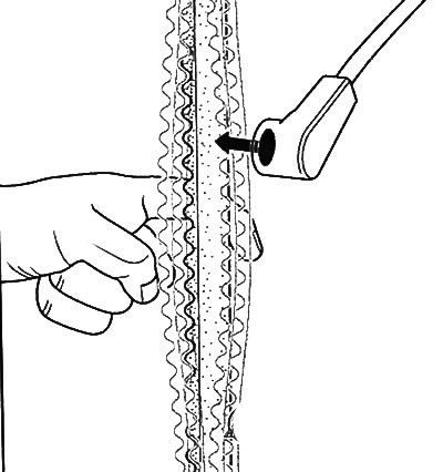
Note: The process of measuring the oscillation frequency is confirmed by the sound signal of the device.
Calibration of tester Mot. 1505
Note:
- It is necessary to calibrate the test equipment monthly.
- Calibration frequency generator (3), embedded in the display block (2), allows you to configure the test device.
1. Turn on the device by pressing the switch (4).
2. Place the sensor (1 A) to the calibration frequency generator (3).
3. Press the test switch (5).
4. Read the value from the instrument display.
5. Check the sensor in the same way (1 V).
6. If the value obtained for both sensors is different from 512± 1 Hz, contact the instrument manufacturer's representative for service.