
Removing the timing belt
Attention: Do not turn the engine crankshaft against the normal direction of rotation.
1. Place the vehicle on a two post lift.
2. Disconnect the negative battery terminal.
3. Remove the front right wheel from the vehicle.
4. Remove the front right fender liner.
5. Remove the motor protective tray.
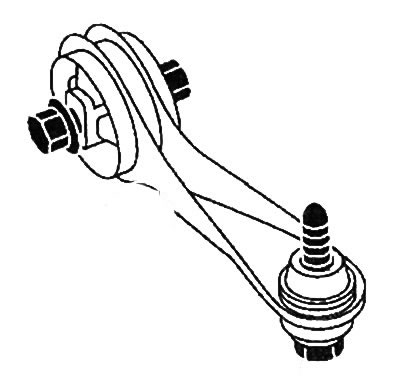
6. Remove engine tie rod.
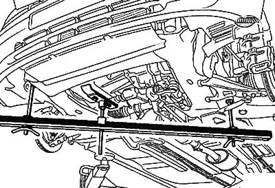
7. Install engine mount (Mot. 1367-02).
8. Remove the right engine mount.
9. Remove attachment drive belts.
10. Remove the crankshaft pulley, securing the flywheel from turning with a screwdriver.
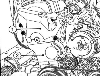
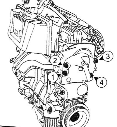
11. Remove the timing cover (1) And (2).
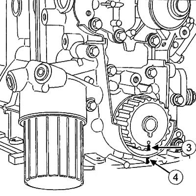
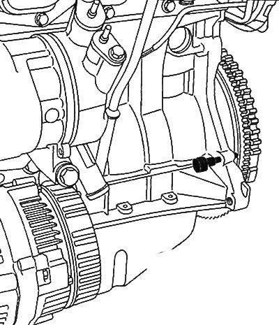
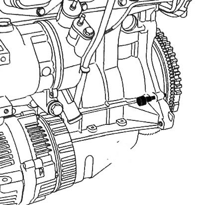
12. Set the engine to TDC using the special dowel pin (Mot. 1054), aligning the label (3) on the crankshaft sprocket with a mark (4).
13. Unscrew the tension roller nut.
14. Remove the timing belt.
Valve timing adjustment
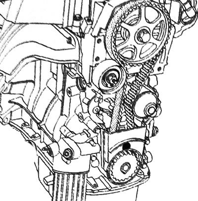
1. Install a new tension roller, making sure that the rib (5) correctly positioned between the two flanges of the idler pulley (6), and the pin (7) tension roller is inserted correctly.
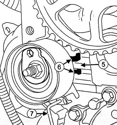
Caution: Do not remove the locking pin (7) tension roller before installing the toothed belt.
2. Tighten the fixing nut of the tension roller by hand until it contacts the tension roller.
3. Make sure that the TDC setting pin (Mot. 1054) is in place.
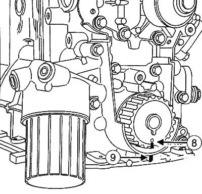
4. Verify that the alignment mark on the sprocket (8) is opposite the label (9) on the oil pump housing.
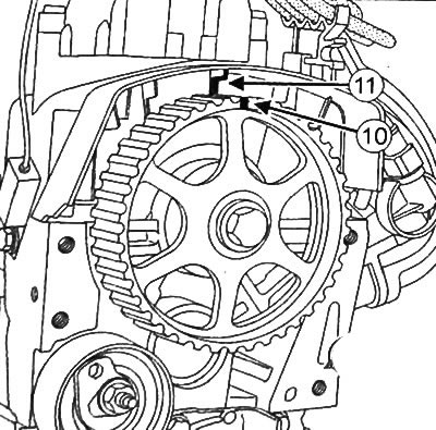
5. Make sure that the mark on the camshaft pulley (10) is opposite the label (11) on the rocker cover.
6. Install the crankshaft pulley bolt and washer to hold the sprocket in place.
Installing the timing belt
Attention: The timing belt must be replaced with a new one after each removal. In addition, it is also necessary to replace the idler pulley and the crankshaft pulley bolt with new ones.
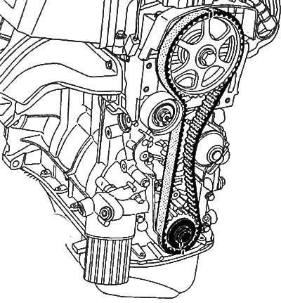
1. Install the timing belt, aligning the marks on the belt with the marks on the camshaft and crankshaft sprockets.
2. Remove the TDC locating pin and tension roller pin.
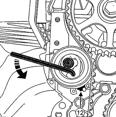
3. With Allen key (hexagon) Turn the eccentric tensioner counterclockwise 6 mm until the tensioner pointer is in the position shown in the figure (12).
4. Tighten the tension roller nut to 24 Nm.
5. Turn the crankshaft six turns clockwise (from the drive side of the gas distribution mechanism).
6. Re-insert TDC locating pin (Mot. 1054) into the flywheel hole and make sure that the timing marks on the camshaft and crankshaft match the fixed marks on the engine.
7. Remove the TDC locating pin.
Note: It is important to tighten the idler nut to the specified torque so as not to damage the idler and at the same time prevent it from becoming loose, which can cause serious engine damage
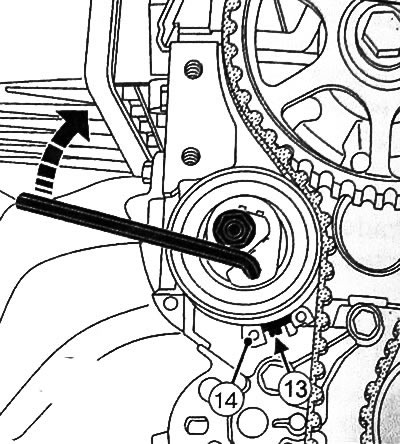
8. Loosen the idler pulley nut no more than one turn while holding the idler pulley in place with an Allen wrench (hexagon) 6 mm, then turn the tension roller pointer clockwise (13) for centering in the setting window (14).
9. Tighten the tension roller nut to 24 Nm.
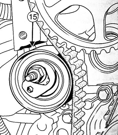
10. Make sure that the tension roller does not touch the cylinder head at the point (15).
Attention:
If the idler pulley touches the cylinder head:
- set the engine to TDC,
- remove the tension roller and the timing belt,
- re-insert the pin of the tension roller,
- repeat the procedure for checking the timing belt from the very beginning.
11. Remove the crankshaft pulley bolt
12. Install the lower timing cover.
13. Tighten bolts of fastening of an intermediate cover of a drive of the gas-distributing mechanism the moment of 10 Нм.
14. Tighten the bolts securing the top cover of the timing gear drive in the sequence shown in the figure to a torque of 33 Nm.
15. With the flywheel secured with a screwdriver, tighten the crankshaft pulley bolt to 40 Nm, then tighten another 150±6' using the magnetized cylinder head tightening indicator lever 'Mot. 591-02) and wrench for angle tightening of the cylinder head (Mot. 591-04).
16. Install the right engine mount and tighten the mounting bolts to 62 Nm.
17. Tighten the engine tie rod bolt to 105 Nm.
18. Tighten the jet thrust mounting bolt on the subframe to 62 Nm.
19. Further installation is carried out in the reverse order of removal.
20. Connect the negative battery terminal.
Tightening torques for threaded connections
| Threaded connections | Torque |
| Tension roller nut | 24 Nm |
| Bolts of fastening of an intermediate cover of a drive of the gas-distributing mechanism | 10 Nm |
| Bolts of fastening of the top cover of a drive of the gas-distributing mechanism | 33 Nm |
| Bolts of fastening of the right mounting support of the engine | 62 Nm |
| Engine tie rod bolt | 105 Nm |
| Bolt of fastening of a support of reactive draft to a subframe | 62 Nm |
| wheel bolts | 105 Nm |