
With the toothed belt removed, the crankshaft or camshaft must not be rotated. Otherwise, the valves will hit the bottom of the pistons and be damaged. If it is necessary to turn the camshaft at a significant angle, then make sure that none of the pistons is at TDC, as this will damage the valves or pistons. If necessary, the crankshaft should be turned to one side or the other by about 90° (1/4 turn) from TDC. In this case, the belt pulley must not rotate more than 90°.
After tensioning the toothed belt, make sure that the TDC marks match the reference marks. If this is not achieved, then the engine is not allowed to start. Otherwise, pistons and valves may collide and cause significant engine damage. If one or more marks do not match, then the installed toothed belt must be removed and the procedure for laying and tensioning it must be completely repeated.
The removed toothed belt cannot be reinstalled. It should be replaced with a new one.
To check the accuracy of the toothed belt tension, the tool RENAULT Mot. 1273, which is also suitable for checking the tension of a wedge or rivet (polyclinic) belts. If such a device is not available, then the tension of the toothed belt can only be performed «approximately». In this case, a tension check should be carried out in a workshop as soon as possible. Before checking, it is recommended to avoid running the engine at high speeds.
If it is not possible to check the tension of the installed toothed belt, it is recommended to perform a test run of the engine with the belt protection cover removed.
Attention! Risk of injury from rotating parts!
Check the belt tension visually. «dancing» the belt indicates that the belt is too loose, and the whistle indicates that it is overstressed.
Attention! Applies to 1.9 and 2.0 liter engines. If the toothed belt tension check is carried out without laying the ribbed belt, then the engine must not be operated for a long time, because it may overheat due to the lack of coolant circulation.
Removing the toothed belt
1. Disconnect the ground wire terminal (-) from the battery. Attention! At the same time, some data is deleted from the memory of storage devices, for example, an access code is erased from the radio receiver, which prevents unauthorized use of the receiver. Before disconnecting the battery, read the instructions in chapter «Removing and installing the battery».
2. Mark with paint the position of the right front wheel on the hub. This will allow you to later set the balanced wheel to its original position.
3. Loosen the wheel bolts. In this case, the wheels of the car must be on the ground.
4. Stand in front of the car on the goats and remove the right front wheel.
5. Remove fender liner (protection) right wheel arch, see relevant chapter.
6. Remove the V-belt, see relevant chapter.
7. Unscrew the mounting bolt and remove the V-belt pulley from the crankshaft. To prevent the crankshaft from turning when the bolt is removed, engage first gear and apply the parking brake.
8. Unscrew the bolts securing the protective cover of the toothed belt and remove it (see illustration).
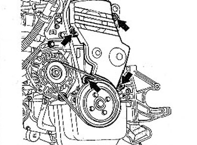
4.8 Unscrew the bolts securing the protective cover of the toothed belt and remove it
9. Screw the V-belt pulley bolt into the center hole of the timing gear and shift into neutral.
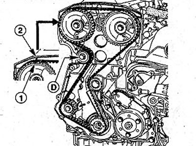
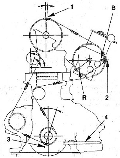
10. Rotate the crankshaft by bolt 8 in the central hole of the gear in the direction of engine rotation until mark 3 on the driven gear 5 of the camshaft matches mark 2 on the cylinder head cover (see illustration). If the indicated marks coincide, cylinder No. 1 will be at TDC.
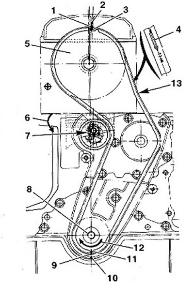
4.10 Rotate the crankshaft by bolt 8 in the central hole of the gear in the direction of engine rotation until mark 3 on the driven gear 5 of the camshaft matches mark 2 on the cylinder head cover
There is another possibility of installing cylinder No. 1 at TDC. To do this, ask the assistant to rotate the front left wheel with the 5th gear engaged.
11. Unscrew clamping nut 7 using a ring wrench (see illustration 4.10).
12. Turn the tension roller against arrow 6, thus loosening the tension of the timing belt (see illustration 4.10).
13. Remove a gear belt. After that, the position of the gears on which it fits, do not change.
Attention! If it is necessary to rotate the camshaft a significant angle, care must be taken to ensure that none of the pistons is at TDC, as this will damage the valves or pistons. If necessary, the crankshaft should be turned to one side or the other by about 90° (1/4 turn) from TDC. In this case, the belt pulley must not rotate more than 90°.
Installation
Attention! The removed toothed belt cannot be reinstalled. It should be replaced with a new one.
14. Lay the new toothed belt so that arrow 4 on its outer side points in the direction of engine rotation. Start laying the belt from the camshaft gear 5, paying attention to the fact that the marks on the gear 3, on the toothed belt I and on the cylinder head cover 2 match (see illustration 4.10). 13 - the point at which the measurement of the degree of tension of the toothed belt should be performed.
15. Lay the toothed belt over the water pump gear and the gear on the crankshaft, and then over the tension roller. At the same time, make sure that the marks on the drive gear 11 of the toothed belt on the crankshaft, on the toothed belt 9 and on the timing gear housing 10 match (see illustration 4.10).
Attention! When laying the toothed belt, it is not allowed to change the position of the camshaft and crankshaft. Changing their position may result in significant engine damage or the engine will not operate at full capacity. After tensioning the belt, check the position of the camshaft and crankshaft again, guided by the reference marks.
16. Turn the belt tension roller 6 in the direction of the arrow as shown in illustration 4.10 and tension the toothed belt.
17. Tighten clamping nut 7 (see illustration 4.10).
Checking/adjusting the tension of the toothed belt with a tester
Specialist workshops use the Mot.1273 tester to check the accuracy of the toothed belt tension (see illustration 4.0).
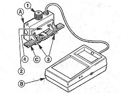
4.0 Specialist workshops use the RENAULT Mot.1273 tester to check the accuracy of the toothed belt tension. A - sensor; B - device; C - toothed belt; 1 - tuning head with knurling; 2 - belt clamp; 3 - stops; 4 - clamping wedge
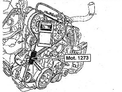
18. Attach the RENAULT Mot. 1273 on toothed belt (see illustration).
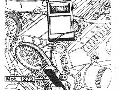
4.18 Attach the RENAULT Mot1273 tester to the toothed belt
19. Loosen the trinity head of the tester three clicks.
20. Loosen the clamp nut on the idler pulley and turn the idler pulley against the timing of the toothed belt until the gauge reads 30 units. Then tighten the clamping nut to 50 Nm. In workshops, to turn the belt tensioner, use tool Mot. 1135-01.
21. Attach the gauge clamp to the belt, and then turn the crankshaft at the center bolt of the toothed belt drive gear three turns in the direction of engine rotation.
22. Recheck the toothed belt tension. If the required nominal value of 30 units±10% is not achieved, then the belt tension adjustment should be repeated again.
Checking/adjusting the toothed belt tension without a tester
Without a tester, the toothed belt can only be tensioned roughly in order to continue driving. As soon as possible, you should contact the workshop to properly check the belt tension. Before performing this check, avoid high engine speeds.
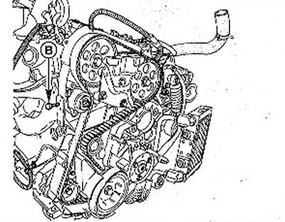
23. Tighten the toothed belt so that it can only be turned by hand by about 90°between the idler pulley and the water pump gear (see illustration).
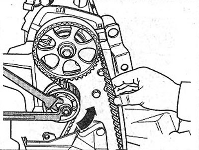
4.23 Tighten the toothed belt so that it can only be turned by hand through approx. 90°between the idler pulley and the water pump gear
24. Tighten the tension roller clamp nut.
25. Check up a deflection of a gear belt. To do this, press on the belt at point 13 (see illustration 4). With a small finger of the hand with a force of about 30 N (about 3 kg). In this case, the belt, if properly tensioned, should sag no more than 6.0±0.5 mm. When performing this operation, ask an assistant to put a ruler on the toothed belt in the segment between the camshaft gear and the water pump gear, and measure the resulting deflection with another ruler.
26. Tighten the toothed belt tensioner nut to 50 Nm.
Attention! The roller nut must be tightened firmly so that it does not loosen when the engine is running, which can cause significant damage to the engine.
27. Turn the crankshaft at the central bolt of the toothed belt drive gear fastening three turns in the direction of engine rotation, and then recheck the belt tension. Repeat tension adjustment if necessary.
28. Make sure that when the belt is tensioned, the piston of cylinder No. 1 is at TDC. This means that labels 1,2 and 3, as well as 9, 10 and 11 must match (see illustration 4. 10). If this is not the case, then remove the toothed belt, lay it again, and then tighten it.
29. Reinstall and bolt the toothed belt cover.
30. Unscrew the central bolt from the crankshaft, which was screwed in to turn it.
31. Put the belt pulley on the crankshaft and secure it with a new bolt with a force of 20 Nm. After that tighten the bolt by 68°±6°. To do this, install a wrench on the bolt head, mark the desired angle of rotation with a goniometer by making a mark on the body with chalk, and then tighten the bolt with a wrench to the desired mark in one continuous movement.
32. Lay the V-belt and tighten it, see the relevant chapter.
33. Replace protection (fender liner) front right fender, see relevant chapter.
34. Reinstall the front wheel, following the marks made during removal. Before installing the wheel, lubricate the disc centering seat on the hub, as well as the cones of the wheel bolts, with a thin layer of bearing grease. The threads of the wheel bolts must not be lubricated.
35. Screw in wheel bolts and lower the car.
36. Tighten the wheel bolts in a cross pattern to 90 Nm.
37. Connect the wire terminal to the battery terminal «masses» (-).
38. Set the clock.
39. Enter, if necessary, the access code to the radio.
Vehicles with 113 hp engine (F3R)
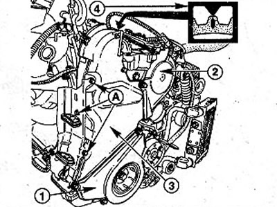
40. Raise the engine with a hoist or crane, securing the cables with carabiner latches on the lugs on the cylinder head. If there is no hoist or crane at your disposal, then pull the cable through the eyes, which, in turn, is fixed on a solid beam or pipe, the ends of which are placed on stands (see illustration).
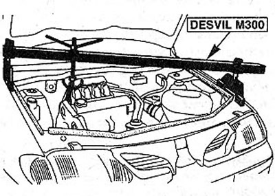
4.40 Pull the cable through the eyelets, which in turn fasten to a strong beam or pipe, the ends of which are placed on stands
Attention! When using a pipe or beam, do not rest its ends on the wings. If necessary, make an additional eye for lifting the engine from the engine compartment, which also fasten to the engine, see the relevant chapter.
41. Remove the plastic protective pad from the base plate of the engine mount.
42. Unscrew bolts of fastening of a support of the engine.
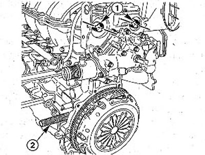
43. Unscrew the bolts 1 and remove the fuel hose holder (see illustration).
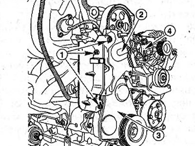
4.43 Unscrew the bolts 1 and remove the fuel hose holder
44. Remove the middle 2 and bottom 3 parts of the toothed belt cover (see illustration 4.43).
45. Unscrew bolts of fastening of an arm 4 support of the engine to a head of the block of cylinders, (see illustration 4.43).
Attention! The toothed belt for this type of engine can only be removed after disconnecting the engine mount bracket.
46. Set the piston of cylinder No. 1 to TDC by turning the crankshaft so that the mark on the camshaft gear is facing vertically up.
47. Remove the plug from the TDC hole on the cylinder block and insert a suitable pin into the hole, for example, Mot.1054 (see illustration). If necessary, turn the crankshaft slightly to one side or the other so that the pin locks the crankshaft in the TDC position.
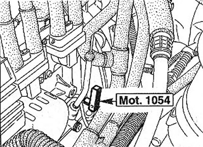
4.47 Remove the plug from the TDC hole on the cylinder block and insert a suitable pin into the hole, for example, Mot.1054
48. Loosen the tightening nut of the toothed belt tension roller.
Attention! The tension of the toothed belt is loosened simultaneously with the loosening of the nut, if the wrench is placed on the nut with the handle up and the nut is unscrewed in one jerk.
49. Lay the toothed belt so that the arrow on it, indicating the direction of movement, is below the tension roller, and the marks on the belt coincide with the marks on the gears of the camshaft and crankshaft.
50. Unscrew the stub bolt from the timing gear housing. Instead of this bolt, screw in bolt D (М6х45) and thus tension the toothed belt (see illustration).
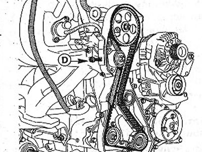
4.50 Screw in bolt D (М6х45) and thus tighten the toothed belt. М6х45=thread diameter 6 mm, bolt length 45 mm
51. Measure the toothed belt tension with the Mot. 1273. The nominal value when measured must be 29 units (see illustration).
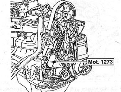
4.51 Measure the toothed belt tension with the Mot. 1273
In the absence of the named device, check the tension of the toothed belt with auxiliary means. When pressing on the belt in the segment between the camshaft gear and the intermediate shaft gear, the belt deflection should be 7.5±0.5 mm with a force of approximately ZON (about 3 kg).
52. Tighten the clamping nut of the toothed belt tensioner roller with a force of 40 Nm.
53. Unscrew the bolt D used for tensioning.
54. Install and fasten the belt pulley to the crankshaft with a bolt tightening of 120 Nm.
55. Remove the pin from the TDC hole and screw in the blind bolt.
56. Replace the timing cover and secure the engine mount bracket.
Vehicles with 150 hp engine (F7R)
57. Remove the trailing arm between the upper suspension strut mounts.
58. Remove mudguard (protection) engine.
59. Attach the engine to the eyelets and raise it slightly to unload the suspension mounts.
60. Remove the engine mount.
61. Disconnect the wire «masses» (-), which connects the engine to the body.
62. Unscrew the bolts of the power steering reservoir and fix it to the body without disconnecting the hoses.
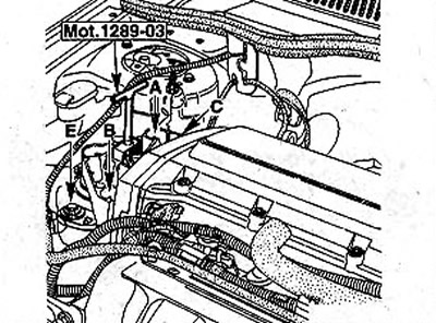
63. Loosen the fastening and disconnect the fuel supply and return hoses. To do this, squeeze the clip from the sides to release the latches A and B (see illustration). If the puller is not on the clamp, use the special tool Mot. 1311 by inserting it from the side into the clip and pushing it down.
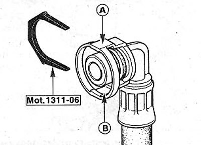
4.63 Squeeze the clip from the sides to release the latches A and B
64. Disconnect the cylinder head cards by bending the holders A (see illustration).
4.64 Disconnect from the cylinder head cover by bending the holders A
65. Disconnect from a final collector a reception pipe, the corresponding chapter see.
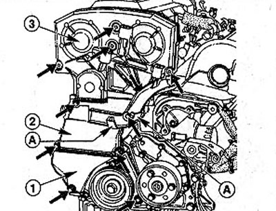
66. Remove covers of a protective casing of a drive of the gas-distributing mechanism. To remove cover 1, you need to unscrew two bolts, and covers 2 - four. Cover 3 is fixed with five bolts (see illustration 4.64). The covers are removed in the order they are numbered.
67. Remove the air filter, see the relevant chapter.
68. Set the piston of cylinder No. 1 to the TDC position. In this case, marks 1 on the gears of the camshafts must coincide with marks 2 on the cylinder head cover (see illustration). At the same time, the mark on the crankshaft drive gear should be set opposite the mark on the timing gear housing.
4.68 Set the piston of cylinder No. 1 to the TDC position. In this case, marks 1 on the gears of the camshafts must coincide* with marks 2 on the cylinder head cover
69. Lock the crankshaft with a punch or pin as it was done for 113 hp engines. (see above).
70. Loosen the tightening nut of the toothed belt tension roller and press the roller away from the toothed belt. If, when loosening the clamping nut, the key is placed with the handle up, and the nut is loosened in one sharp movement, then the tension of the toothed belt is also loosened.
71. Lay the toothed belt so that the arrow E, indicating the direction of belt movement, is below the tension roller, and the marks on the toothed belt coincide with the marks on the gears of the camshafts and crankshaft (see illustration).
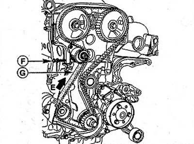
4.71 Lay the toothed belt so that the arrow E, indicating the direction of movement of the belt, is below the tension roller
72. Unscrew the stub bolt from the timing gear housing. Instead of this bolt, screw in bolt D (М6х45) and thus tighten the toothed belt, M6x45 = thread diameter 6 mm, bolt length 45 mm (see illustration 4.71).
73. Press at point O with your thumb on the toothed belt to distribute the belt tension (see illustration 4.71).
74. Install, while maintaining the achieved position of the belt, the sensor of the belt tension measuring device at point G (see illustration 4.71).
Test instrument Mot. 1273 should register a nominal toothed belt tension of 32±3 units.
In the absence of a control and measuring device, the nominal deflection when checking the tension of the toothed belt when pressing the belt in the segment between both gears of the camshafts with a force of 30 N (about 3 kg) should be 3±0.5 mm.
75. Tighten the tension roller clamp nut to 50 Nm.
76. Unscrew the bolt that tensioned the belt and screw the cap bolt into place.
77. Reinstall and secure with bolts and parts of the timing cover. Start installing covers from the top.
78. Install the V-belt pulley on the crankshaft and secure it with a bolt with a force of 100 Nm.
79. Put on the nozzles and fix the fuel hoses with clips.
80. Lay in the guide and clamp the hoses on the cylinder head cover with clamps.
81. Reinstall and bolt the power steering reservoir.
82. Connect the wire «masses» (-), connecting the engine to the body.
83. Connect a reception pipe to a final collector, the corresponding chapter see.
84. Reinstall the engine mudguard.
85. Remove the pin that fixed the crankshaft in the TDC position of cylinder No. 1, and plug the hole with a plug.
86. Screw on the engine mount cover. Tighten the fastening bolts in the sequence A, B, C with a force of 40 Nm (see illustration).
4.86 Screw on the engine mount cover. Tighten the fastening bolts in the sequence A, B, C with a force of 40 Nm
87. Fix the adjusting tool on the vibration limiter and tighten both bolts E with a force of 60 Nm (see illustration 4.86).
88. Fix a cross-beam between the top support of amortization racks.
89. Replace the air filter.
Diesel vehicles
90. Lift the engine by the lugs and remove the engine mount as indicated for 113 hp engines. (see above).
91. Install the No. 1 cylinder piston at TDC. To do this, rotate the crankshaft by the central bolt of the belt pulley in the direction of engine rotation until the mark on the camshaft gear coincides with mark 4 on the cover (see illustration).
4.91 Rotate the crankshaft by the central bolt of the belt pulley in the direction of engine rotation until the mark on the camshaft gear coincides with mark 4 on the cover
92. Remove the lower part I of the protective cover of the gas distribution mechanism (see illustration 4.91).
93. Remove poly wedge (brook) belt, see relevant chapter.
94. Lock the crankshaft with the appropriate pin or punch (see above).
95. Disconnect the holder A of the fuel hose (see illustration 4.91).
96. Unscrew the bolts securing the remaining parts 2 and 3 of the timing cover and remove them (see illustration 4.91).
97. Loosen the tightening nut of the tension roller and release the toothed belt.
Attention! The tightening nut should be loosened no more than one turn. Otherwise, the tension roller may fall out.
98. Lay a new toothed belt so that the TDC marks of the piston of cylinder No. 1 on the following parts coincide (see illustration).
4.98 Lay a new toothed belt so that the following TDC marks on the piston of cylinder No. 1 coincide on the belt and on
1 - camshaft gear
2 - injection pump gear. Attention! Depending on the model, the position of the injection pump drive gear may differ. B = Bosch injection pump, R = Lucas injection pump
3 - drive gear on the crankshaft
4 - holes for the pin / punch for fixing the crankshaft must match
99. Unscrew the plug bolt from the side of the timing gear housing. Instead of this bolt, screw in bolt B (М6х45) and thus tighten the toothed belt. M6x45 = thread diameter b mm, bolt length 45 mm (see illustration).
4.99 Unscrew the plug bolt from the side of the timing gear housing and screw in bolt B
100. Measure the toothed belt tension. When measured with the tester RENAULT Mot. 1273 nominal value should be 38 units (see illustration).
4.100 Measure the toothed belt tension using the RENAULT Mot. 1273
The nominal value of the belt deflection when tensioning without using a control and measuring device by pressing the toothed belt in the middle of the belt section between the camshaft gear and the injection pump gear should be 6±1 mm with an applied force of approximately 30 N (about 3 kg).
101. Tighten the tension roller clamp nut to 50 Nm.
102. Unscrew the bolt with which the toothed belt was tensioned.
103. Install on the crankshaft and bolt the belt pulley. Bolt tightening torque 120 Nm.
104. Remove the pin that fixed the crankshaft in the TDC position of cylinder No. 1, and screw the plug bolt into this hole.
105. Reinstall the engine mount bracket and adjust the vibration limiter using tool Mot. 1289-03 (see illustration).
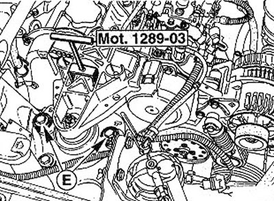
4.105 Reinstall the engine mount bracket and adjust the vibration limiter using tool Mot. 1289-03
106. Fix the spacer bar between the upper supports of the shock absorber struts.
107. Contact a workshop to check the start of injection pump supply.
Only Scenic cars
108. Remove the wiper arms, see the relevant chapter.
109. Remove fairing pads (see arrows in illustration).
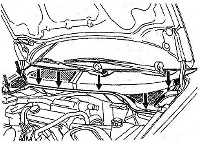
4.109 Remove fairing trims (see arrows)
110. Fix on the eyes a device for lifting the engine from the engine compartment (see illustration). Tie the beam of the device with straps to the front pillars.
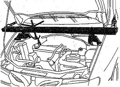
4.110 Attach the device to lift the engine from the engine compartment
Only vehicles with 1.4-/1.6-litre petrol engines (K4J/K4M)
Attention! The timing gear on the crankshaft and driven gears on the camshafts must not be removed. This is possible only in the workshop. Due to the fact that special tools from RENAULT will be required to perform all the work, it is recommended that you carefully read the contents of this chapter before performing them. This is necessary to make a decision on the possibility of performing the necessary work on their own.
111. Remove protective covers from the top support of fastening of amortization racks to mudguards.
112. Unscrew the connecting bolt 5 (see illustration), and then a connecting cover with three nuts.
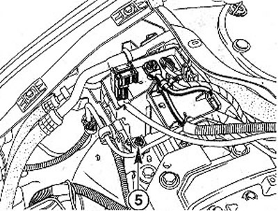
4.112 Unscrew the connecting bolt 5
113. Disconnect plug 3 and wire terminal 4 (see illustration).
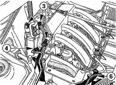
4.113 Disconnect plug 3 and wire terminal 4
114. Loosen the bolt 6 fastening the wiring harness (see illustration 4.113).
115. Release the wiring harness from the top of the toothed belt guard.
116. Release the fuel lines from the holders on the bottom of the toothed belt guard.
117. Remove the plugs from the ends of 1 camshafts by punching the plugs with a screwdriver (see illustration). Plugs must be replaced with new ones after each dismantling.
4.117 Remove the plugs from the ends 1 of the camshafts by punching the plugs with a screwdriver. Plugs are not shown in the illustration
118. Turn the engine clockwise by the belt pulley on the crankshaft. The grooves on the ends of the camshafts must be installed as shown in illustration 4.117.
119. Unscrew the cover bolt 2 (Mot. 1489) from the hole for fixing the crankshaft in the TDC position of cylinder No. 1 and insert the appropriate pin to the stop or screw in the bolt (see illustration 4.117).
120. Rotate the crankshaft clockwise until it rests against the inserted locking pin. The grooves on the ends of the camshafts must be installed horizontally.
121. Fix the crankshaft in this position by inserting a screwdriver into the splines of the flywheel.
122. Remove the belt pulley bolt and remove it from the crankshaft.
123. Unscrew the bolts with which the protective cover of the V-belt is attached to the longitudinal beam in the engine compartment, and remove it.
124. Unscrew bolts of fastening of the bottom and top parts of a protective cover of a gear belt and remove them.
125. Loosen the toothed belt tension by unscrewing the nut 1 on the toothed belt tension roller (see illustration).
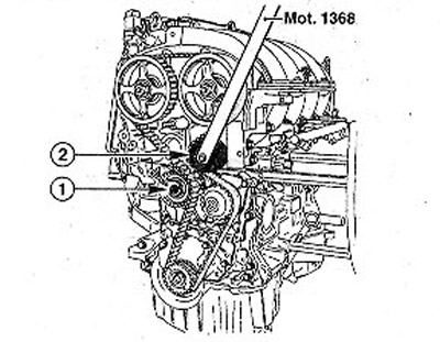
4.125 Release the toothed belt tension by unscrewing nut 1 on the toothed belt tension roller
126. Remove guide roller 2 using tool Mot. 1368 or with a 50 Tox curved wrench (see illustration 4.125).
Attention! Make sure that when removing the toothed belt from the crankshaft, the drive gear does not fall off.
Attention! Before installing the parts in place and assembling, remove the gear from the crankshaft and remove any grease from the gear and V-belt pulley seat. Otherwise, it may cause significant engine damage.
The toothed belt tension roller and guide roller must be replaced after each disassembly.
127. Make sure that the grooves at the ends of the camshafts are horizontal.
128. Attach tool Mot. 1496 (see illustration).
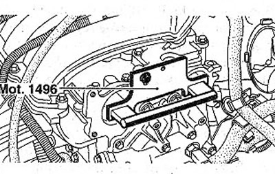
4.128 Fix tool Mot.1496 in the grooves of the camshafts
129. Be convinced that a cranked shaft adjoins to a pin which fixes it in the TDC position of the cylinder No. 1. In this position, the groove at the end of the crankshaft must face up.
130. Install a new toothed belt tensioner on the support pin and only slightly tighten the fastening nut. The roller pin must fit into the corresponding groove.
131. Lay a toothed belt.
132. Install the guide roller and secure it with tool Mot. 1368. Roller tightening torque is 45 Nm (see illustration 4.125).
Toothed belt tension - adjustment
133. Move arrow A in the direction as shown in the illustration, using a 6 mm key, inserting it into hole B. Arrow A should protrude relative to the fixed arrow 7 by 7-8 mm and be located as shown in the illustration.
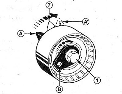
4.133 Turn arrow A in the direction as shown in the illustration using a 6 mm wrench, inserting it into hole B
134. Tighten the bolt 1 of the tension roller with a force of 7 Nm (see illustration 4.133).
135. Install the belt pulley on the crankshaft and secure it with a bolt. However, the bolt should not be fully tightened. This means that a distance of 2-3 mm should remain between the bolt head and the pulley.
Attention! The previous pulley bolt can be reused if its length does not exceed 49.1 mm. Lubricate the old bolt with oil before installation. The new bolt must not be lubricated.
136. Tighten the belt pulley bolt on the crankshaft with a force of 20 Nm. After that tighten the bolt by 135°±15° (3/8 turn). The crankshaft must still remain in the fixed position.
137. Remove the pin that fixed the crankshaft in the TDC position of cylinder No. 1, and remove the stop ruler from the camshafts.
138. Turn the crankshaft two turns. In this case, before completing the second turn, screw in bolt Mot. 1489 and seat the crankshaft against this bolt. With the crankshaft in this position, remove the lock bolt.
139. Loosen the belt tensioner nut a maximum of one turn, holding it with a 6mm Allen wrench.
140. Align the movable arrow A relative to the fixed arrow 7 (see illustration 4.133) and tighten the tension roller while maintaining this position, applying a force of 27 Nm.
141. Turn the crankshaft two turns. Once cylinder #1 is at TDC, both arrows on the timing belt tensioner should line up.
If you screw in the stop bolt that fixes the crankshaft at the TDC of cylinder No. 1, then the Mot ruler can be installed on the ends of the camshafts. 1496 (see illustration 4.128). Otherwise, the adjustment must be repeated.