If the valve clearance is too small, the valve timing changes, compression deteriorates, engine power drops, and the engine becomes uneven. In extreme cases, this can lead to valve deformation or burnout. Valve seats can also burn out.
With an increased valve clearance, strong mechanical noises appear in the operation of the engine, and the valve timing changes. Due to incomplete filling of the cylinders, the power and stability of the engine is reduced.
Adjusting the valve clearance will achieve the desired result if the valves themselves are tight, have no play in the guides, and the valve plates are not broken.
The valve clearance must be checked and adjusted, as a rule, after repair or when noise appears in the valve drive. Checking the valve clearance is not included in the maintenance.
Valve clearance must be checked and adjusted with a cold engine.
Attention! The type of motor must be taken into account when checking or adjusting the clearance. For vehicles with a 150 hp engine. the valve clearance is not adjustable, because hydraulic poppets are installed there, which automatically correct the gap.
To check or adjust the gap, the corresponding valve must be unloaded. This is possible when turning the camshaft, which can be turned in several ways.
- 1st way. Place the vehicle on a level surface. Engage 5th gear and release the parking brake. Push the car forward or backward. Jack up the front of the car from the side.
- 2nd way. Engage 5th gear, tighten the parking brake lever. Jack up the vehicle so that one of the front wheels can be rotated. Turn the raised front wheel by hand.
- 3rd way. Place the vehicle on a level surface. Engage neutral gear and apply the parking brake. Rotate the crankshaft by the central bolt of the belt pulley - using the socket head.
Attention! To make the engine easier to crank, you can unscrew the spark plugs.
Vehicles with a 1.4-/1.6-liter petrol engine (E7J/K7M)
Examination
1. Remove the air filter, see relevant chapter.
2. Disconnect the accelerator cable from the throttle valve and put it away from the place of work, see the relevant chapter.
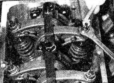
3. Disconnect the low pressure hose 2 on the cylinder head cover (see illustration).

10.3 Disconnect the low pressure hose 2 on the cylinder head cover
4. Disconnect plug 2 by squeezing the wire clamp (see illustration 10.3).
5. Unscrew the bolts (see arrows in illustration 10.3) and remove the cylinder head cover
The sequence of valves in the cylinder head is as follows: EA-EA-AE-AE. The letter A indicates the exhaust valves, and the letter E indicates the intake valves (see illustration 10.0).
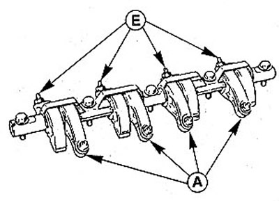
10.0 The sequence of valves in the cylinder head is EA-EA-AE-AE. The letter A indicates the exhaust valves, and the letter E indicates the intake valves
Recognizing the valves is easy enough because the intake valves are on the intake manifold side and the exhaust valves are on the exhaust side.
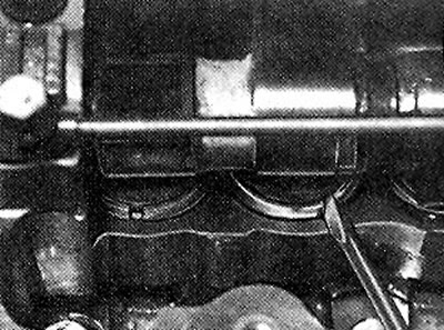
6. Rotate the camshaft until the #1 cylinder exhaust valve is fully open. Cylinder #1 is on the left side near the flywheel. Cylinders are arranged in sequence from 1 to 4, counting from the gearbox to the V-belt. The valve is fully open when the rocker pushes the valve down (see left side of illustration). In this camshaft position (Cylinder #1 Exhaust Valve Fully Open) you can adjust the clearance of the inlet valve of cylinder No. 3 and the exhaust valve of cylinder No. 4 (see illustration 10.6).
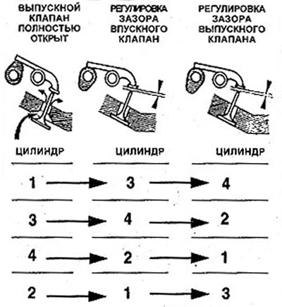
10.6 The valve is fully open when the rocker pushes the valve down (see left side)
7. Measure the valve clearance by inserting a gauge between the rocker arm and the end of the valve stem.
Valve clearance ratings (for a cold engine):
- intake valves - 0.10 mm
- exhaust valves - 0.25 mm
Attention! A cold engine is an engine temperature corresponding to the air temperature, approximately +20°C.
The valve clearance is adjusted correctly if the gauge can be inserted and removed with some force and a sound similar to the suction of air is heard.
8. Move the vehicle again slightly to open the exhaust valve of cylinder #3 and adjust the clearances for the intake valve of cylinder #4 and exhaust cylinder #2 (see illustration 10.6).
In the same way, check and adjust the clearances of all other valves.
Adjustment
9. Loosen the jam nut approximately 1/2 turn with a 10mm wrench or 10mm socket wrench if the valve clearance cannot be set to nominal (see illustration). At the same time, keep the adjusting screw from turning by the flats with a smaller wrench or pliers. For 1.6 liter engines, in these cases you will need a socket wrench for Tox head bolts.
10.9 Loosen the jam nut approximately 1/2 turn with a 10 mm wrench or ring spanner if the valve clearance cannot be set to nominal
10. Adjust the valve clearance by turning the adjusting screw with a wrench or pliers.
11. Fix the set gap by tightening the locknut.
12. Check again the set clearance, and then rotate the engine to adjust the clearance of the next valve and thus check and adjust the clearances of all valves.
Attention! It is recommended to mark the rocker arms of already adjusted valves with a marker.
13. After completing the adjustment of the valve clearances, check the position and fit of the clamping brackets on the ends of the rocker arm axis (see illustration).
10.13 After completing the adjustment of the valve clearances, check the position and fit of the clamping brackets on the ends of the rocker shaft
14. Reinstall and bolt the cylinder head cover. Do not overtighten the bolts as this will crush the cover gasket and cause it to leak.
15. Connect injection system plugs.
16. Connect a low pressure hose to a branch pipe near a cover of a head of the block of cylinders.
17. Fasten the accelerator cable to the throttle valve and adjust it, see the relevant chapter.
18. Replace the air filter, see relevant chapter.
Vehicles with a 113 hp petrol engine. and diesel engine
Examination
19. Remove the cylinder head cover.
20. Establish a camshaft so that valves of the cylinder No. 1 were evenly turned down, the left part of an illustration 10.20 see. In this position, the intake and exhaust valves of cylinder No. 1 are in the overlapping phase. Cylinder number 1 is located near the flywheel. In this case, the valve cams of cylinder No. 4 are turned up (see right side of illustration 10.20).
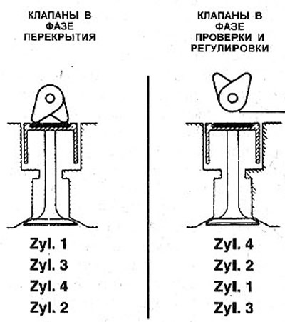
10.20 Install the camshaft so that the valves of cylinder No. 1 are evenly facing down, see the left side of the illustration
21. Check the valve clearance of cylinder #4 by inserting a gauge between the poppet shim and the rounded part of the camshaft cam (see illustration). The gauge must enter the gap according to the principle of a retracting movement. Otherwise, the gap should be adjusted.
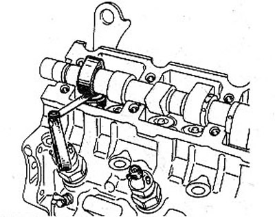
10.21 Check the valve clearance of cylinder #4 by inserting a gauge between the poppet shim and the round part of the camshaft cam
To adjust the valve clearance, measure the existing clearance with a gauge. To do this, measure with gauges until you find the right one. Record the resulting valve clearance.
Attention! Consider the sequence of inlet and outlet valves. E - intake valves, A - exhaust (see illustration).
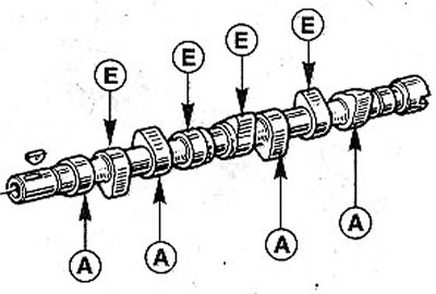
10.21a Consider the sequence of inlet and outlet valves. E - intake valves, A - exhaust
Valve clearance ratings (for a cold engine):
- intake valves - 0.20 mm;
- exhaust valves - 0.40 mm.
Attention! A cold engine is the temperature of the engine corresponding to the air temperature.
22. Again move the vehicle slightly so that the valves of cylinder No. 3 are in the overlapping phase and adjust the valve clearances of cylinder No. 2.
23. Check up backlashes of valves of other cylinders, acting in sequence, as shown in an illustration 10.20.
Adjustment
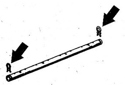
24. Turn the pusher so that the groove on it faces forward (see illustration).
10.24 Rotate the pusher so that the groove on it faces forward
25. Adjust the valve clearances by replacing the shims 1 on the poppets 2 (see illustration). To replace the washers, the bucket tappets should be pressed out with a clamping device 3.
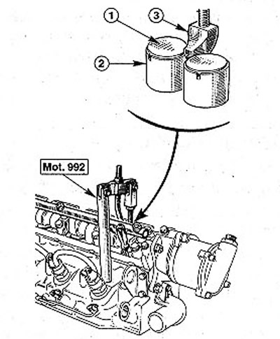
10.25 Adjust the valve clearances by replacing the shims 1 on the poppets 2
Attention! In view of the fact that the clamping device must correspond exactly to the distance between the poppets, the RENAULT Mot. tool is required for this purpose. 992.
26. Press the poppet and remove the adjusting washer with a screwdriver, scriber or magnet.
27. Measure with a micrometer (with bracket) the thickness of the removed shim. Record the result. The thickness of the washer is indicated on its underside (see illustration).
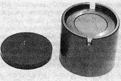
10.27 Measure with a micrometer (with bracket) the thickness of the removed shim. Record the result. The thickness of the washer is indicated on its underside
28. Moisten a new adjusting washer in engine oil and install it in the pusher.
Attention! When installing the washer, make sure that the side with the embossed marking is facing down. The scope of delivery includes shims with a thickness of 3.25 mm to 4.30 mm in increments of 0.05 mm, as well as washers 4.40 mm and 4.50 mm.
29. Replace the shims on the remaining pushers in the same way and check the valve clearances.
Attention! Adjusting washers can be reused if there are no visible signs of wear on them, for example, the thickness of the washer embossed on the underside is not readable.
30. Reinstall the cylinder head cover and its gasket. Tighten the cover bolts with a force of 10 Nm. If the cover gasket has become porous or flattened, replace the gasket with a new one.
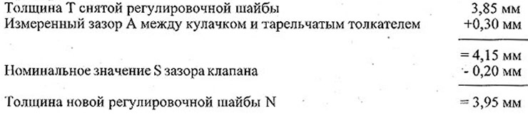
Use the following formula to calculate the thickness of a new shim:
N=T+ (A - S)
N = new gasket thickness
T = thickness of the removed gasket
A = measured value of valve clearance
S = nominal valve clearance
Example: