
Vehicles with a 1.4-/1.6-liter petrol engine (E7J/K7M)
Removal and installation of the oil pan are shown on the example of a 1.4-/1.6-liter gasoline engine (E7J/K7M) with steel pallet. To dismantle the aluminum pallet, it is necessary to remove the power unit.
Attention! For removing the oil pan of a 1.4-/1.6-litre petrol engine (K4J/K4M) it is necessary to remove the parts of the hydraulic drive of the power steering. For this reason, the pallet can only be removed in a workshop environment.
Removing
Attention! Some pallet removal work is described in more detail in chapters «Engine - removal and installation», and «Gearbox - removal and installation». For this reason, it is also recommended to familiarize yourself with the provisions of these chapters.
1. Disconnect the wire terminal «masses» (-) from the negative pole of the battery.
Attention! This deletes data from the memory devices, for example, the security code of the radio. Read the chapter's recommendations «Battery - removal and installation».
2. Remove a broad tank of a cooling liquid and hang it on the thermostat case under the top hose from a radiator.
3. Disconnect the upper coolant circulation hose from the thermostat housing, collecting the leaked fluid. Before disconnecting the hose, loosen the clamp and slide it onto the hose.
4. Mark the position of the front wheels on the hub with paint. This will allow the assembly to set the balanced wheel in its original position.
5. Loosen the wheel bolts. In this case, the car must be on the ground.
6. Install the front of the car on the goats and remove the front wheels.
7. Remove, if available, mudguard (protection) engine.
8. Drain the engine oil, see relevant chapter.
9. Remove wheel arch liners, see relevant chapter.
10. Disconnect from a final collector a reception pipe and the catalyst, the corresponding chapter see.
11. Disconnect the shift fork rod on the gearbox, see the relevant chapter.
Left side of the car
12. Remove a support of the brake mechanism of the left forward wheel and fix it with a wire on an amortization rack, the corresponding chapter see.
13. Press out a finger of a tip of cross steering draft from the lever of a rotary fist by means of a stripper, the corresponding chapter see.
14. Unscrew the three bolts securing the CV joint boot of the left axle shaft to the gearbox.
15. Unscrew a nut of a spherical support and take a clamping bolt.
16. Disconnect the transverse lever from the hub by pushing it down. If the lever does not give in, then squeeze the lever with a mount, inserting it between the bottom and the lever.
17. Unscrew two bolts of fastening of the bottom part of an amortization rack to a nave.
18. Give a rotary fist outside. In this case, the axle shaft will be released from the gearbox.
Attention! Do not allow a significant angle of inclination of the drive shafts, because this can cause damage to the anthers of the CV joints.
Right side of the car
19. Knock out the tension pin of the right axle shaft with a suitable punch, see the relevant chapter.
20. Press out a finger of a tip of cross steering draft from the lever of a rotary fist by means of a stripper, the corresponding chapter see.
21. Unscrew the upper bolt securing the lower part of the shock absorber to the hub, and only loosen the lower nut, do not completely unscrew it.
22. Give a rotary fist outside. In this case, the right axle shaft will be released from the gearbox.
23. Secure the axle shaft with wire on the steering gear (see illustration).
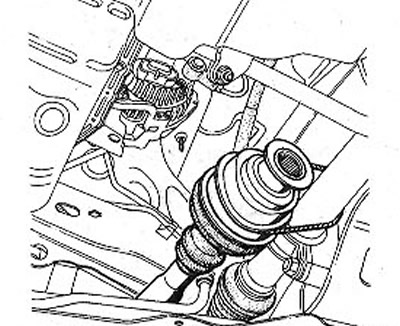
19.23 Fasten the axle shaft with wire to the steering gear
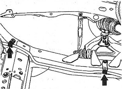
24. Unscrew the nut 1 of the engine and gearbox support (see illustration).
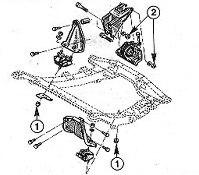
19.24 Unscrew the nut 1 of the engine and gearbox support
25. Unscrew the nuts 2 of the stabilizing arm (see illustration 19.24).
26. Disconnect the wire «masses» (-), connecting the engine to the body.
27. Disconnect from the gearbox, if any, the tachometer drive shaft.
28. Disconnect the power steering reservoir and set it aside from the work site without disconnecting the hoses from the reservoir.
29. Disconnect the vacuum brake booster hose from the intake manifold by cutting the clamp with side cutters. When installing, secure the hose to the intake manifold with a new clamp.
30. Disconnect the hose from the canister solenoid valve.
31. Disconnect the crankcase ventilation hose.
32. Disconnect the plug from the throttle opening angle potentiometer.
33. 1.6 liter petrol engine (K7M). Loosen the fuel feed line on the fuel filter and disconnect it. To do this, press on the side of the clamp to raise the clamps A and B. If there is no puller on the clamp, then use the special tool Mot.1311-06, inserting it from the side into the clamp and pressing (see illustration).
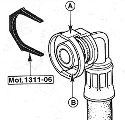
19.33 Use the special tool Mot.1311-06 by inserting it from the side into the clamp and pressing
34. 1.4 liter petrol engine (E7J). Label the fuel lines with tape to ensure they are properly installed during reassembly.
35. Disconnect the supply and return fuel lines, after loosening the fastening clamps. When disconnecting hoses, place a rag to collect escaping fuel. Seal fuel lines with suitable plugs immediately after disconnection. For these purposes, you can use clean bolts of the appropriate diameter.
36. 1.6 liter petrol engine (K7M). Attach eyelet A to the cylinder head to lift the engine (see illustration).
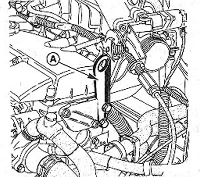
19.36 Attach lug A to the cylinder head to lift the engine. 1.6 liter petrol engine (K7M).
If necessary, the eyelet can be made independently, using the proposed drawing (see illustration 19.0).
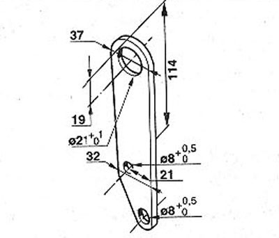
19.0 Engine lifting lug drawing
37. Release the clutch cable from the attachment to the longitudinal beam.
38. Release the power steering hose from the mountings on the carrier beam and lay it aside from the work site. To do this, you will need to remove the retaining fasteners (see illustration).
19.38 Release the power steering hose from the mountings on the carrier beam and put it aside from the place of work
39. Attach two hoist carabiners to the engine lugs. If there is no such lift, then fix the cable in the eyes and put a sufficiently thick pipe on which you fasten the ends of the cable. Support the ends of the pipe on stands (see illustration).
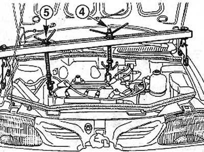
19.39 Attach two carabiners of the hoist to the engine lugs. If there is no such lift, then fix the cable in the eyes and put a sufficiently thick pipe on which you fasten the ends of the cable
Attention! Do not rest pipe ends on wings.
40. Scenic cars. Raise the engine.
41. Raise the engine with a hoist to unload the supports and unscrew the three bolts 6 of the bracket (see illustration).
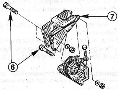
19.41 Raise the engine with a hoist to unload the supports and unscrew the three bolts 6 of the bracket
42. Remove bracket 7 of the engine mount by pushing it down (see illustration 19.41).
43. Raise the engine from the side of the toothed belt so that the distance between the cylinder block and the carrier beam A is 26 cm (see illustration). To lift this side of the engine, tighten bolt 5 of the lift (see illustration 19.39).
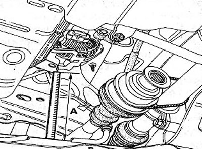
19.43 Raise the engine on the toothed belt side until the distance between the cylinder block and carrier A is 26 cm
Attention! When lifting the engine, make sure that the fuse box wiring harness does not get caught or pinched between the gearbox (5th gear fork) and longitudinal beam.
44. Unscrew bolts of fastening of the oil pallet and disconnect it, as it is shown by an arrow on an illustration. If necessary, gently pry it out with a screwdriver.
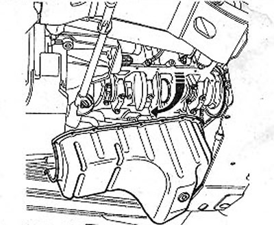
19.44 Unscrew the bolts of the oil pans, disconnect it, as shown by the arrow in the illustration
Installation
45. Remove seal residues from the oil pan and cylinder block with a grease solvent and dry them. Alcohol or acetone can be used as a cleaning agent.
46. Thoroughly wipe the cylinder block, crankshaft drive and oil pump. Otherwise, the sealing of the oil pan may be insufficient due to oil that has entered from these parts.
47. Apply, as shown in the illustration, RHODORSIL 5661 sealant in a strip 1 three mm thick on the sealing surface of the oil pump.
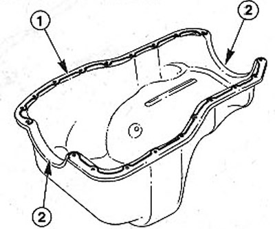
19.47 Apply, as shown in the illustration, RHODORSIL 5661 sealant in a strip 1 three mm thick on the sealing surface of the oil pump
48. Insert 2 new sealing rubbers into the recesses at the ends (see illustration 19.47).
49. Make sure that no oil has dripped onto the sealing surfaces before connecting the sump. If necessary, remove the oil with a rag, and wipe the place with a solvent.
Attention! The use of a solvent is mandatory. Simply rubbing is not enough.
50. Carefully put the oil pan back in place. If at the same time the sealant layer is displaced, then remove the pallet and correct the sealant layer in the right place.
51. First screw in the two middle bolts, tightening them by hand, and then screw in all the other bolts, remembering to put washers on them.
52. Tighten the oil pan bolts evenly with a slight tightening force, maximum 10 Nm.
53. Replace the engine mount bracket and lower the engine so that the three mounting bolts can be inserted. Screw nuts onto the bolts, do not tighten them yet.
54. Fasten the power steering hose to the carrier frame with holders.
55. Fasten the clutch cable to the longitudinal beam, see the relevant chapter.
56. Unscrew the fixed lug from the engine to lift it.
57. Connect and fix fuel hoses with collars.
58. Connect the throttle potentiometer plug.
59. Connect the crankcase ventilation hose.
60. Connect the hose to the canister solenoid valve.
61. Connect the vacuum brake booster hose to the intake manifold pipe and secure it with a clamp.
62. Replace the power steering reservoir.
63. Connect, if available, the tachometer shaft to the gearbox.
64. Connect the wire «masses» (-), connecting the engine and body.
65. Replace the spacer between the upper suspension strut mounts.
66. Tighten the nuts of the engine and gearbox mounting bracket. Don't over tighten them.
67. Install the power block on supports without stress, pushing it from side to side, and tighten all the bolts and nuts for fastening the supports with the necessary force, see chapter «Engine Mount».
68. Connect the shift fork rod, see the relevant chapter.
69. Connect to a final collector a reception pipe with the catalyst, the corresponding chapter see.
70. Replace the drive shafts, see the appropriate chapter.
71. Connect the tie rod ends.
72. Replace the ball joint connecting the transverse lever and the steering knuckle, see the relevant chapter.
73. Replace the brake caliper, see the relevant chapter.
74. Establish forward wheels according to the marks put at removal. Before doing this, lubricate the wheel disc seat on the hub with a thin layer of bearing grease. Do not lubricate the threads of the wheel bolts. Bolt the wheels and lower the car.
75. Tighten the wheel bolts in a cross pattern to 90 Nm.
76. Connect the upper hose-cooling fluid to the thermostat housing and secure it with a clamp.
77. Replace the coolant reservoir.
78. Check the coolant level and top up if necessary, see the relevant chapter.
Attention! Wait approximately one hour. This time is necessary for the sealant to cure.
79. Top up the engine oil and check the level with the dipstick.
80. Connect wire terminal «masses» (-) to the negative pole of the battery.
81. Set the clock.
82. Enter, if necessary, the security code into the radio.
83. Carry out a test drive and check the tightness of the oil pan. If necessary, carefully tighten the pan mounting bolts.
Only vehicles with a 2.0 liter petrol engine (except 16 valve engine), with 1.9 liter diesel engine
84. Remove the cover from the vibration damper on the engine mount.
85. Unscrew the bolt 1 of the stabilizer strut (see illustration).
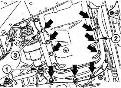
19.85 Unscrew bolt 1 stabilizer mount
86. Unscrew the bolts of the support 2 of the power unit (see illustration 19.85).
Attention! Due to the difficult access, bolt 3 will need to be unscrewed using a shortened T50 socket with the simultaneous use of an 8 mm overhead wrench.
87. Tighten the oil pan bolts evenly to 15 Nm.
88. Adjust the engine mount torsional vibration damper after the engine is lowered onto the stands and secure the stands.
Attention! Removing and installing the oil pan on vehicles with a 1.4-/1.6-liter petrol engine (K4J/K4M) should be entrusted to a workshop, because the parts of the power steering are dismantled.