
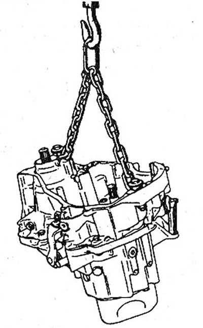
The gearbox is removed from the engine compartment by lifting it up. Due to the fact that when dismantling the box, it is necessary to disconnect the threaded connections on the bottom of the car, four stand goats, as well as a garage lift, will be needed to complete the work. When disconnecting the box from the engine, it will need to be lifted, so a crane or hoist is needed.
Attention! For vehicles with a 2.0-litre petrol engine and diesel engines, the base frame must first be dismantled. To dismantle the frame, a special RENAULT trolley is required so that the frame does not fall after unscrewing the fixing bolts. For this reason, it is recommended to remove the power unit by lifting upwards.
Regarding the removal of the gearbox on vehicles with a 1.4-/1.6-litre petrol engine (K4J/K4M), here, too, the base frame must first be removed, as in vehicles with a 2.0-liter gasoline engine. Therefore, for these vehicles, it is recommended to remove the power unit by lifting it up.
Vehicles with a 1.4-/1.6-liter petrol engine
1. Disconnect the ground wire terminal (-) from the battery.
Attention! At the same time, some data is deleted from the memory of storage devices, for example, an access code is erased from the radio receiver, which prevents unauthorized use of the receiver. Before disconnecting the battery, read the instructions in chapter «Removing and installing the battery».
2. Mark with paint the position of the front wheels on the hubs. This will allow you to later set the balanced wheel to its original position.
3. Loosen the wheel bolts. In this case, the wheels of the car must be on the ground.
4. Install the scaffolds in front of the car and remove the front wheels.
5. Remove, if available, mudguard (protection) engine.
6. Drain the transmission oil from the box, see the relevant chapter.
7. Remove the connecting posts between the transverse and trailing arms on each side of the vehicle (see arrows in illustration).
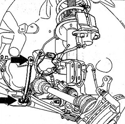
1.7 Remove the connector posts between the transverse trailing arms on each side of the vehicle (see arrows)
8. Remove the calipers of the left and right front brakes and secure them with wire on the suspension struts, see the relevant chapter.
Left side of the car
9. Unscrew the nut of the ball joint pin of the left tie rod end, and then press the pin out of the mount on the steering knuckle with an appropriate puller (see illustration).
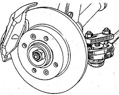
1.9 Unscrew the nut of the ball joint pin of the left tie rod end
10. Unscrew three bolts of fastening of a cuff of SHRUS of the left semiaxis to a transmission.
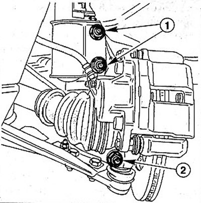
11. Unscrew nut 2 and remove clamping bolt (see illustration).
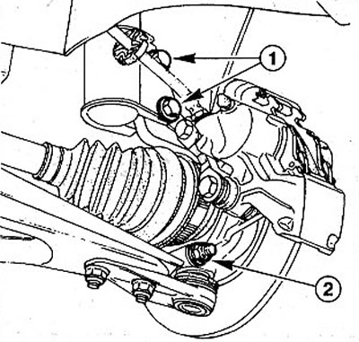
1.11 Unscrew nut 2 and remove clamping bolt
12. Disconnect the transverse suspension arm from the hub by pushing it down. If the lever does not give in, then use the mount, setting it between the bottom and the lever.
13. Unscrew the two bolts 1 that secure the lower part of the shock absorber to the hub (see illustration 1.11).
Right side of the car
14. Knock out the spacer pin of the right axle shaft using a suitable punch with a diameter of 3 mm (see illustration).
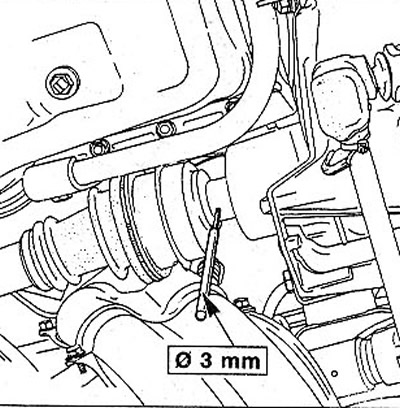
1.14 Knock out the spacer pin of the right axle shaft using a suitable punch with a diameter of 3 mm
15. Unscrew clamping bolt 2 (see illustration).
1.15 Unscrew clamping bolt 2
16. Disconnect the transverse suspension arm from the hub by pushing it down. If the lever does not give in, then use the mount, setting it between the bottom and the lever.
17. Unscrew the two bolts 1 that secure the lower part of the shock absorber to the hub (see illustration 1.15).
18. Give a rotary fist outside. In this case, the axle shaft will come out of the connection with the gearbox (see illustration).
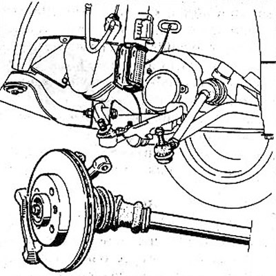
1.18 Move the steering knuckle out
Attention! Do not allow significant bending of the CV joints, so as not to damage the cuffs.
19. Unscrew bolts of fastening of the holder of the pipeline of the hydraulic booster of a steering (see arrows in illustration).
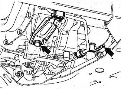
1.19 Unscrew the bolts of the holder of the power steering pipeline (see arrows) •
20. Unscrew the bolts securing the protective cover of the clutch H, as well as both bolts C of the power unit support (see illustration).
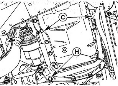
1.20 Unscrew the bolts securing the protective cover of the clutch H, as well as both bolts C of the power unit support
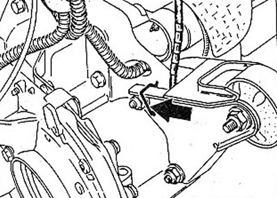
21. Unscrew the bottom nut of the engine/gearbox mounting flange (see illustration).
1.21 Unscrew the bottom nut of the engine/gearbox mounting flange
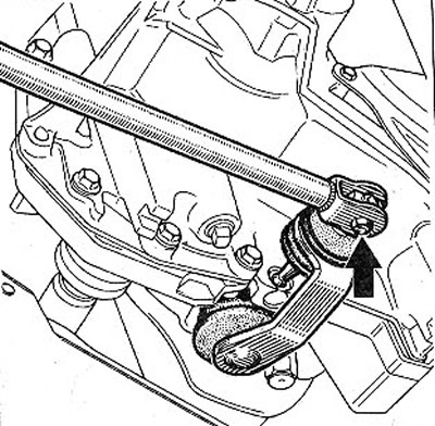
22. Disconnect, if present, the clamp (see arrow in illustration) and disconnect the tachometer drive cable from the gearbox. If the tachometer cable is missing, then disconnect the speedometer plug at the gearbox.
1.22 Disconnect if available; clamp (see arrow) and disconnect the tachometer drive cable from the gearbox
23. Disconnect the clutch cable from the gearbox by pulling the cable in the direction of the arrow, as shown in the illustration.
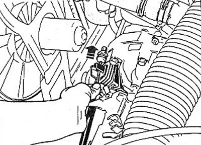
1.23 Disconnect the clutch cable from the gearbox by pulling the cable in the direction of the arrow
24. Disconnect the power wire of the reversing lights on the gearbox.
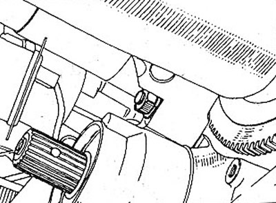
25. Unscrew a bolt of fastening of a rod of a choice of transfers (see arrow in illustration), by pulling out the protective cuff.
1.25 Unscrew the bolt securing the gear selector rod (see arrow), pressing out the protective cuff
26. Disconnect from an exhaust manifold a reception pipe of mufflers.
27. Raise the engine with a crane to unload the rear suspension support.
28. Disconnect the gearbox rear suspension bracket.
Separation of the engine and gearbox
29. Remove the starter, see the relevant chapter.
30. Unscrew bolts of fastening of the engine and transmission.
31. Unscrew pins A and B (see arrows in illustration). To do this, you will need two nuts with the appropriate threads, a box wrench with a curved handle and an articulated wrench. Screw one nut onto the finger, and lock it with the second. Turning the first nut, unscrew the pin, holding it from turning by the lock nut.
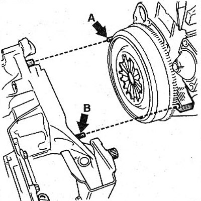
1.31 Unscrew pins A (see arrows)
32. Slightly lower the raised power unit and use a pry bar to disengage the engine and transmission. At the same time, drive the box with the 5th gear housing between the longitudinal beam and the carrier frame.
33. Raise the engine to its original position.
34. Fasten the cables to the box by screwing the two mounting bolts into the connecting flange (see illustration).
1.34 Fasten the cables to the box by screwing the two mounting bolts into the connecting flange
Attention! To prevent the clutch release bearing from disengaging when the transmission is removed, install a suitable pipe between the clutch release fork and the clutch cable lug.
35. Slightly tilt the gearbox forward and remove it from the engine compartment. If necessary, use the services of an assistant.