



Install the B. Vi. 1581 mounting plate onto the Desvil stand.
Install the gearbox on the mounting plate B. Vi. 1581.
Remove the clutch release slave cylinder.
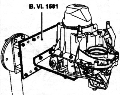
Unscrew the bolts located inside the crankcase.
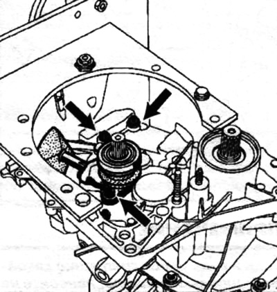
Remove the rear cover. It should be removed along the horizontal axis of the box, as it includes a capsule with grease located in the hole of the primary shaft.
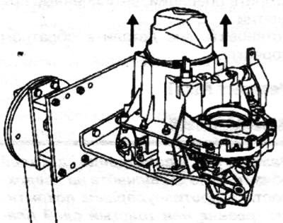
Engage first gear with the gear shift lever and fifth gear by sliding its fork along the rod.
Remove the secondary shaft bolt and the primary shaft nut.
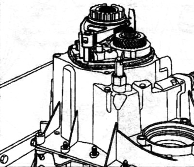
Using tool B. Vi. 31-01 (punch), knock out the fifth gear fork pin.
 |
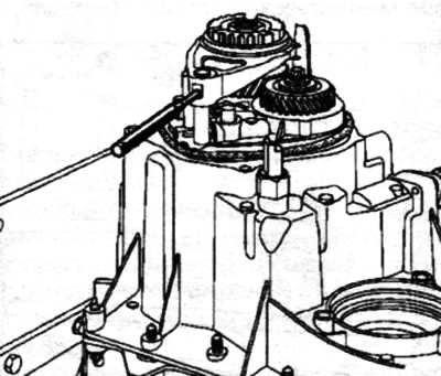 |
Remove the fifth gear fork and clutch.
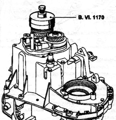
Remove the fifth gear hub using tool B.Vi. 1170.
Set the toothed clutch of the B.Vi. 1170 device to the position of the engaged fifth gear, turning it so as to align the splines of the toothed clutch and the hub, and remove the device together with the hub.
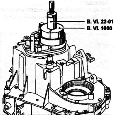
Remove the fixed fifth gear pinion using tools B.Vi. 22-01 and B.Vi. 1000.
Remove the outer transmission case bolts.
Remove the speed sensor B (for semi-automatic gearbox JH1).
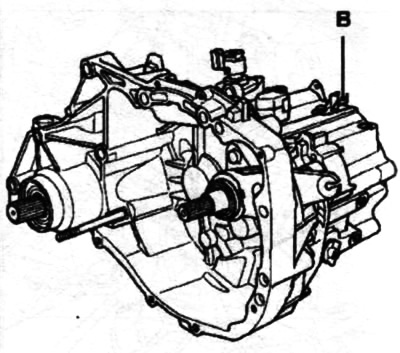
It is recommended to install two magnets or cover the C holes in order not to lose the balls and springs that fix the ½ and 3/4 rods.
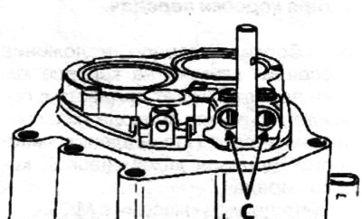
Remove the reverse rod A and reverse contactor B.
Press the shift rod outward.
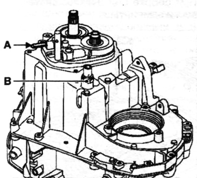
Disconnect and remove the gearbox housing.
Turn the reverse gear shaft assembly to the left and remove the reverse/fifth gear shift fork rod.
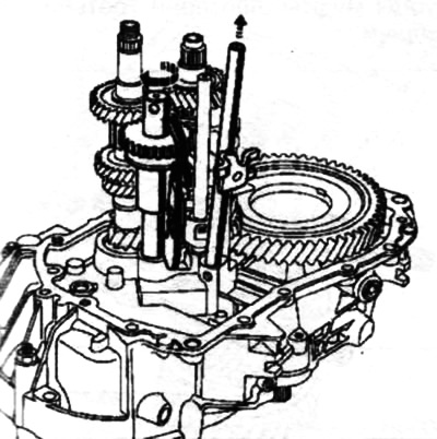
Raise the input shaft slightly and remove the reverse gear shaft assembly.
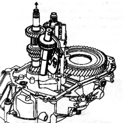
Disconnect the 3/4 fork pins using tool B. Vi. 949 and remove the 3/4 fork and stem assembly.
At the same time, remove the primary and secondary shaft assembly with the rod and ½ fork.
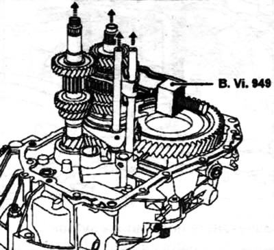
Remove locking pins A and B.
Removal gears
Clamp the secondary shaft in a vice with jaws, then remove all gears.
When removing and installing snap rings, use snap ring pliers on one end and circlip pliers on the other.
Checking the details
The teeth of the gears and couplings must not be too worn and must not have any nicks.
Also, make sure that there are no signs of friction or excessive wear on the shaft surfaces and the inner surfaces of the gears.
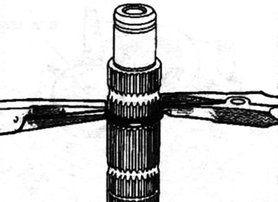
It is recommended to mark the position of the gear couplings relative to the hubs.
Installing a group of gears
Perform installation in the reverse order of removal.
The retaining rings must be replaced regularly.