
Attention! Disassembly and placement of parts must be carried out on a surface with an anti-shock coating (rubber or thick plastic).
Removing
Install mounting plate (B.VL.1581) on the rack (Desvil).
Install the gearbox on the mounting plate (B.VL1581).

Remove the clutch release cylinder.
Loosen the bolts located inside the crankcase.
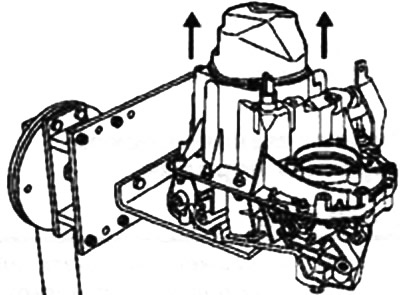
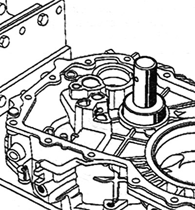
Remove the rear casing strictly along the horizontal axis of the box, as it includes a lubricant capsule located in the input shaft hole.
Engage first gear with the shift lever, and fifth gear by sliding its fork along the stem.
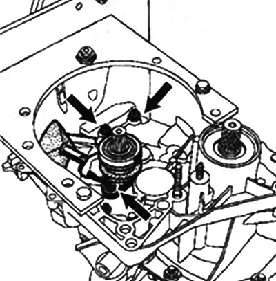
Turn out a bolt of a secondary shaft and turn away a nut of an input shaft.
With the help of a core (B.Vi.31-01), knock out the fifth gear fork pin.
Remove the fork and fifth gear clutch.
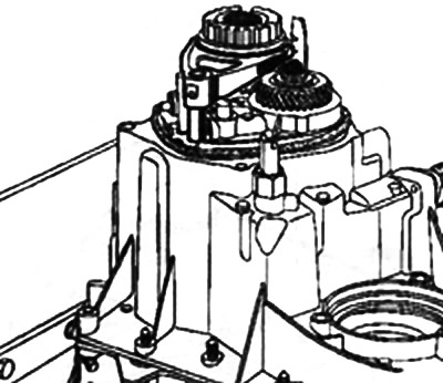
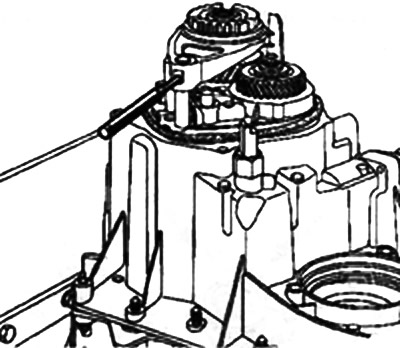
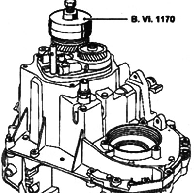
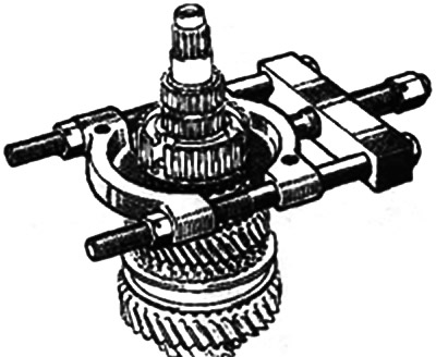
Remove the 5th gear hub using the tool (B.VL1170).
Install gear coupling tool (B.VU170) to the engaged fifth gear position by turning it so as to align the splines of the gear coupling and the hub, and remove the tool together with the hub.
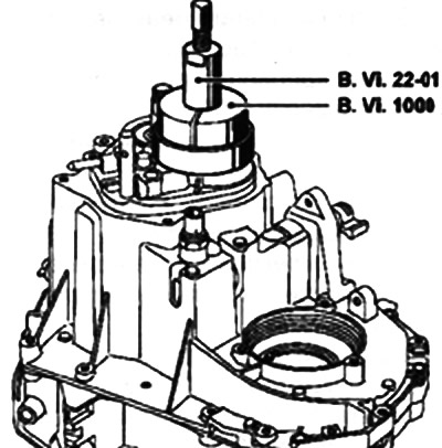
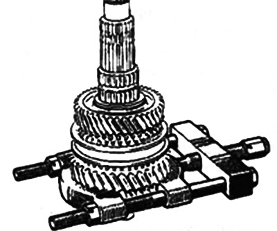
Remove the fixed 5th gear using tools (B.VJ.22-01 and B.Vi.1000).
Remove the outer crankcase bolts.
Remove speed sensor B (for semi-automatic transmission JH1).
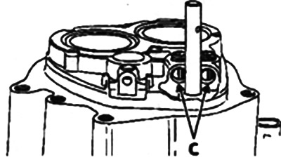
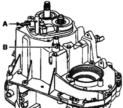
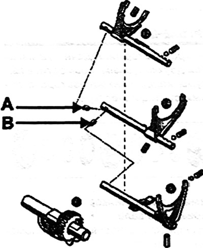
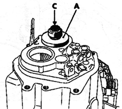
It is recommended to install two magnets or cover holes C in order not to lose the balls and springs for fixing the rods 1/2 and 3/4.
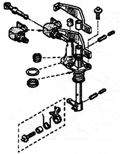
Remove reverse stem A and reverse contactor B.
Press on the shift rod with a force directed outward.
Disconnect and remove the box crankcase.
Rotate the reverse axle assembly to the left and remove the shift fork stem «reverse/fifth gear».
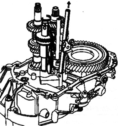
Raise the input shaft slightly and remove the reverse gear axle assembly.
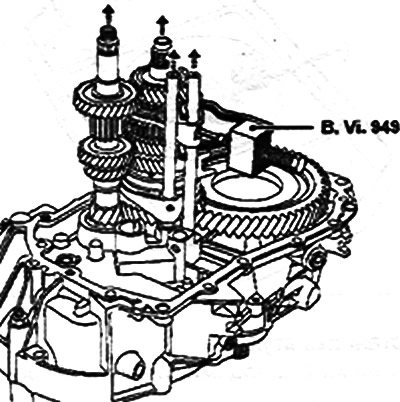
Disconnect the 3/4 yoke pins using the tool (B.VL949) and remove the 3/4 stem and yoke assembly.
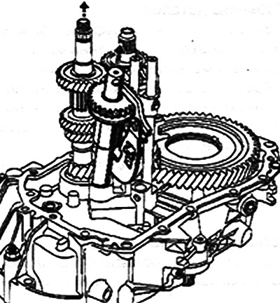
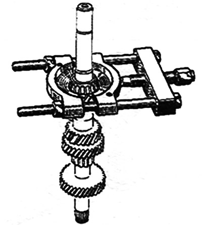
At the same time, remove the input and output shaft assembly with the stem and yoke 1/2.
Remove pins A and B.
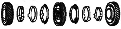
Removing gears
Clamp the output shaft in a vise with jaws, and then remove all gears.
When removing and installing circlips, use circlip pliers on one side and pliers on the other.
Checking details
Gear and clutch teeth must not be excessively worn or serrated.
Also, make sure that the shaft surfaces and the inner surfaces of the gears do not show signs of friction or excessive wear.
It is recommended to mark the position of the gear couplings relative to the hubs.
Gear group installation
Install in the reverse order of removal.
Retaining rings must be systematically replaced.
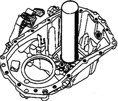
Replacing bearings in the crankcase
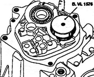
Spread the circlips with appropriate pliers and press the bearing into the crankcase using the tool (B.Vi.1576).

Installation
Install new circlips in their seats.

Note. There are two types of snap rings: input shaft A and output shaft B.
Install bearings with tool (B.VL1576).
Insert the bearing fixture with a hammer.
Replacing bearings on the clutch housing side
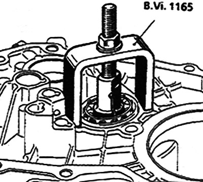
Cut off the plastic capsule located in the center of the bearing at the base.
Install fixture (B.Vi.1165) and remove the bearing.
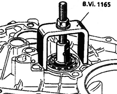
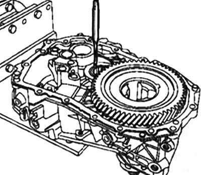
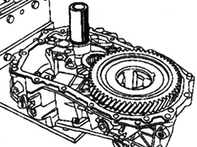
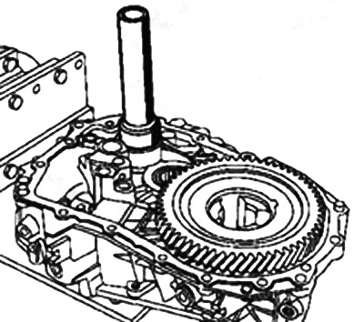
Installing the bearings on the clutch housing side
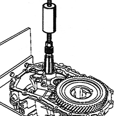
Install the deflector and then press in the bearing, aligning it with the inside of the crankcase.
Chisel the bearing.
Remove the input shaft centering bearing using a 38 mm bushing.
Install the center bearing with the tool (B.Vi.1601).
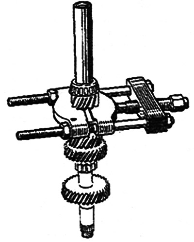
Removing gears
Bushings under gears 2nd, 3rd. 4th gear installed with an interference fit. During assembly, they must be systematically replaced.
Using a press, remove the assembly «ring, hub and third gear». Rely on the teeth of the third gear clutch.
Using a press, remove the assembly «bushings and gears for 1st and 2nd gears. hub, gear coupling». Rely on the first gear for this.
Checking details
Gear and clutch teeth must not be excessively worn and must not have any nicks.
Also, make sure that the shaft surfaces and the inner surfaces of the gears do not show signs of friction or excessive wear.
It is recommended to mark the position of the gear couplings relative to the hubs.
Gear group installation
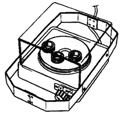
For assembly it is necessary to use a heating plate having a mode of 150°C.
Place new bushings on a cold hot plate. Warm them up for 15 minutes with a thermostat. set to 150°C.
Bushing installation
Remove the bushing from the heating plate with tongs and install it on the shaft using a bushing with an inner diameter of 33 mm. Keep it up until then. until she hits the hub.
Note. The 1/2 gear synchronizer is double cone; align the protrusions of the synchronizer rings with the grooves of the hubs and gears.
Replacing input shaft bearings
Press out the bearings with a puller.
Press in the bearings using a 25 mm bushing.
Remove the output shaft bearing cone with a puller.
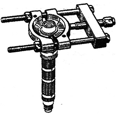
Set the cone in place with a press.
Push out the bearing outer races from the crankcase side using a 55 mm bushing.

Install the bearing outer races on the crankcase side using a 60 mm diameter bushing.
Replacing the bearing on the clutch housing side
Cut off the plastic capsule located in the center of the bearing at the base.
Install fixture (B.Vi.1165) and remove the bearing.
Install bearing with tool (B.Vi.1167).
Push out the input shaft bearing outer race from the clutch housing side using a 38 mm puller.
Press in the bearing race using a 46 mm bushing.
Adjustment of a preload of bearings of a secondary shaft
Note. Adjust only when bearings are replaced.
Install output shaft into clutch housing with bearings and pre-adjustment ring (V.Vi. 1161) or similar ring 1.60 mm thick (large outside diameter).
Install crankcase.
Wrap and tighten bolts of a socket of a box.
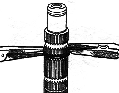
Install the dial indicator bracket plate (B.VL1161) (or similar) on the tripod body mounts.
Install special bushing (VL/I527) A and bolt C.
Install a pointer type indicator with a magnetic base.
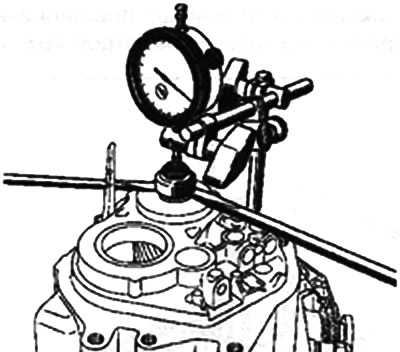
Rotate the output shaft a few times to make sure the bearings are in place.
Set zero on the indicator scale.
Using two screwdrivers as levers, pull up the output shaft.
Read the pointer type indicator.
Repeat these operations several times in the same sequence.
Determine the average value of the obtained values.
Calculate the thickness of the preload adjustment ring using the following calculation formula:
prescribed value + thickness of the preload ring + average value of the pointer gauge = thickness of the preload ring.
Example (values in mm):
prescribed value 0.26 + thickness of the pre-adjustment ring 0.49 + average value of the dial indicator 1.60 = 2.35.
Note. A set of shims 2.15-2.43 mm thick in 0.04 mm increments is supplied as a replacement.
Adjusting the axial clearance of the output shaft bearings
Note. Adjust only when bearings are replaced.
Install input shaft with bearings and pre-adjustment ring (B.Vi.1161) 0.62 mm thick (small outside diameter).
Install differential housing, install and tighten box connector bolts and indicator bracket plate (B.Vi.1161) on the tripod body mounts.
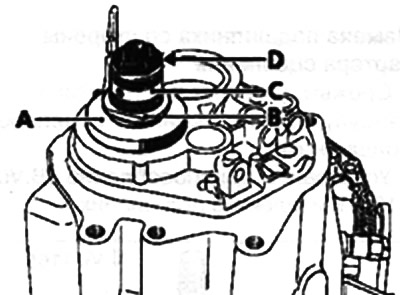
Install:
- sleeve (B.Vi.1527) A;
- support ring B;
- gear ring C;
- nut fully screwed in D.
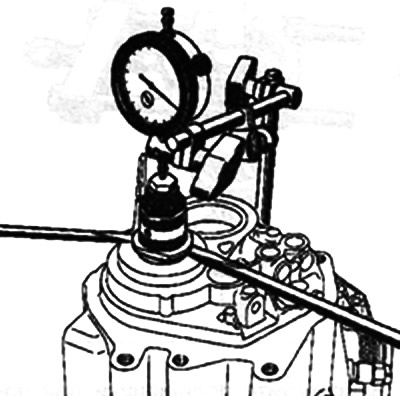
Install a pointer type indicator with a magnetic base.
Rotate the input shaft a few times to make sure the bearings are in place.
Set zero on the indicator scale.
Using two screwdrivers as levers, pull up the input shaft.
Read the pointer type indicator.
Repeat these operations several times in the same sequence.
Determine the average value of the obtained values.
Calculate the thickness for the preload adjustment ring using the following calculation formula:
ring thickness for pre-adjustment + average value of pointer-type indicator readings - 0.02 (this value must be subtracted to ensure the minimum clearance) = thickness of the ring to be adjusted.
Example (values in mm):
- ring thickness for pre-adjustment 0.62 + average value of pointer type indicator readings 0.50-0.02 (this value must be subtracted to ensure the minimum clearance) = thickness of the adjustment ring 1.10.
Note. A set of shims 0.86-1.30 mm thick in 0.04 mm increments is supplied as a replacement.