
The assembly-disassembly process requires special equipment - pullers, indicators, hydraulic press, etc.
Spare parts for the box are often difficult to obtain, many of them are unreasonably expensive.
Based on these considerations, if faults are found in the gearbox - noise, jamming or difficulty when shifting gears, vibration, etc. it is advisable to entrust the repair of the box to specialists or purchase a remanufactured box for replacement.
For the reasons stated below, the operations available for independent performance by a motorist will be described below.
Removal and installation of the mechanism of a gear change
Removing
- place the car on a lift or raise the front of the car and install safety supports under the body;
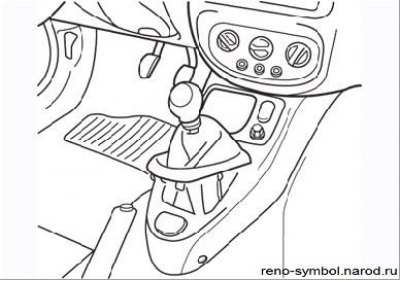
Figure 4.24. Removal of a cover of the handle of the gear lever
- inside the vehicle, carefully remove the shift lever cover from the console (Figure 4.24);
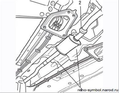
Figure 4.25. Removing the fastening of heat-insulating shields (1) and collar (2), connecting the front and rear parts of the exhaust system
- remove the heat shields under the vehicle and disconnect the rear of the exhaust system from the front (Figure 4.25). Rack up the back of the system;
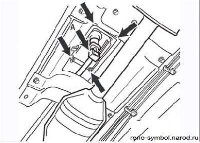
Figure 4.26. Removing the shift lever housing: And – a nut of a rod of switching; arrows show four nuts securing the body to the floor of the body
- remove the nut, remove the washer and disconnect the shift rod from the bottom of the shift lever. Loosen the four nuts securing the shift lever housing to the floor and lower it down (Figure 4.26);
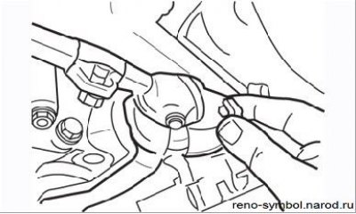
Figure 4.27. Shift rod mounting assembly
- bend the rubber boot, unscrew the bolt in front of the stem, remove the washer and bushing (Figure 4.27). Remember the location of the parts (Figure 4.28). Remove the stem from the gearbox;
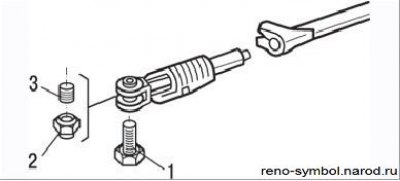
Figure 4.28. Shift rod mounting details: 1 - bolt; 2 - nut; 3 - bushing
- before removing the fork of the mechanism, mark its position relative to the stem, loosen the clamp bolt and disconnect the fork;
- inspect parts - replace worn or damaged parts.
Installation
- lubricate the pivot joints of the gear lever and the axle of the gearshift linkage with grease 33 Medium;
- install the fork on the stem, as noted during removal, and securely tighten the clamp;
- if you are installing new parts, then when installing the fork on the stem, make sure that approximately 7–8 mm of the corrugated part of the fork is visible; the fork should be facing the protruding part towards the gearbox;
- attach the fork to the gear lever, install the bushing, bolt and nut;
- perform the remaining operations in the reverse order of removal;
- check and adjust the gearshift mechanism.
Attention! For fine adjustment of the movement, tool B.Vi is required. 1133 - locking gear lever in the first gear position.
Adjustment of the mechanism of a gear change
Operating procedure:
- place the car on a lift or raise the front of the car and install safety supports under the body;
- remove the protective cover of the power unit;
- remove the heat shields to gain access to the gearshift lever;
- turn on the first gear in the gearbox;
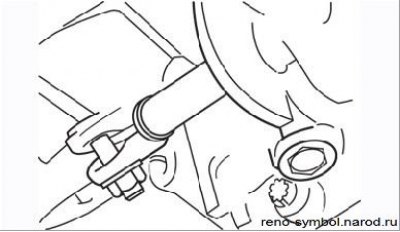
Figure 4.29. Adjusting collar on the shift rod on the side of the gearbox
- loosen the clamp bolt on the gearshift shaft on the transmission side so that the shaft can move (Figure 4.29);
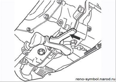
Figure 4.30. Installing the B.Vi. 1133 (arrow)
- to hold the shift lever in the first gear position, install the B.Vi detent. 1133 (Figure 4.30). In the absence of such a tool, you can independently make a suitable replacement from a metal strip or piece of board;
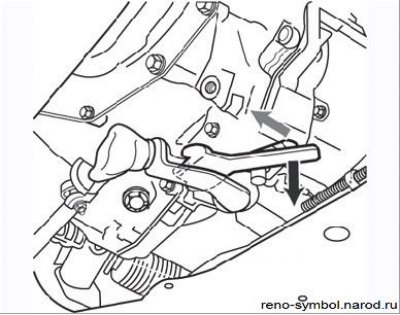
Figure 4.31. Pull the latch down and rotate it 45° (the arrow shows the clamp bolt)
- at the same time pull the end of the template down and turn it at an angle of approximately 45°until it touches the groove on the gearbox housing (Figure 4.31);
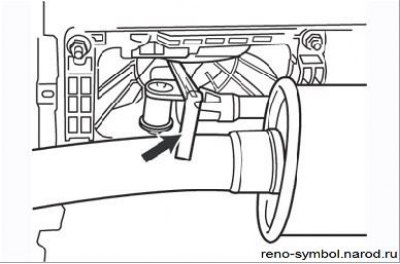
Figure 4.32. Gap adjustment 9.0 mm in the gearshift drive (the arrow shows the probe)
- move the shift lever so that a 9 mm thick flat feeler gauge can be inserted between the thrust ring on the lever and the wedge-shaped plate on the housing (Figure 4.32). In this position, tighten the bolt (see Figure 4.31);
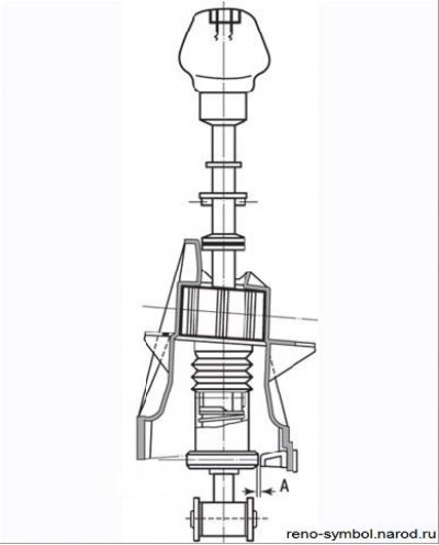
Figure 4.33. Gap (A) between lever and body
- check the obtained gap A, which should be equal to 7–10 mm (Figure 4.33);
- remove the B.Vi template. 1133;
- check the correct gear engagement;
- install the protective pallet of the power unit;
- lower the car.
Check, removal and installation of the reverse light switch
The reverse light switch is screwed into the left side of the gearbox housing behind the front wheel drive shaft pivot. Before removing the switch for replacement, check the integrity of the F3 fuse on the block in the car.
You can check the operation of the switch using the tester in the mode «dialing», for which disconnect the contact connector from the switch and check, by setting the reverse gear, that the switch is working.
If the switch is defective, unscrew it and replace it with a good one by installing a new sealing washer. If part of the oil leaked out of the box during the replacement, bring its level to normal.
Replacing the input shaft seal
It is impossible to replace the oil seal without disassembling the gearbox, since the clutch release bearing guide sleeve is pressed into the housing and removed inside the gearbox. For these reasons, it is better to entrust the replacement of the oil seal to specialists.