
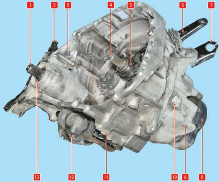
Manual Transmission: 1 - side gear shank; 2 - speed sensor; 3 - clutch housing; 4 - input shaft; 5 - clutch release bearing; 6 - clutch release fork; 7 - emphasis on the sheath of the clutch release drive cable; 8 - back cover; 9 - gearbox housing; 10 - oil filler plug; 11 - oil drain plug; 12 - gear shift mechanism; 13 - epiploon of a shank of the right semi-axial differential gear
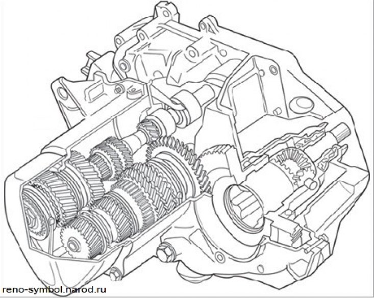
Figure 4.14. Sectional view of a manual transmission
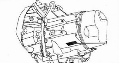
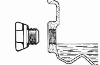
Identification plate (1) located on the crankcase of the box, see figure.
 | 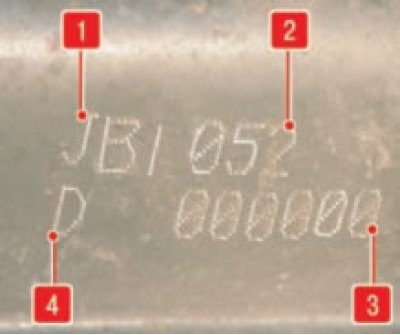 |
Gearbox identification data: 1 - type of gearbox; 2 - modification of the gearbox; 3 - serial number of the gearbox; 4 - manufacturer's code
The manual transmission of the JB1 model is five-speed, all forward gears are synchronized. The main gear and the differential mechanism are built into the gearbox.
Gearbox specification:
- Filling capacity - 3.4 liters
- Oil level - under the edge of the filler hole
- Transmission oil type - TRX 75W, 80W
Single Use Details:
- Oil seals.
- Rubber sealing rings.
- Thrust bearing guides.
- Nuts of fastening of primary and secondary shaft.
- Speedometer drive shaft and gear.
- Guide pins.
Table. gear ratios
| Engine | Differential | speedometer drive | Broadcast | Reverse | ||||
| 1st | 2nd | 3rd | 4th | 5th | ||||
| K4J | 15/61 | 21/19 | 11/37 | 22/41 | 28/37 | 34/35 | 39/31 | 11/39 |
| K7J | 14/63 | 21/19 | 11/41 | 21/43 | 28/37 | 30/29 | 41/31 | 11/39 |
Table. Lubricants, sealants and adhesives
| Name | Purpose |
| MOLYKOTE BR2 | Lubricate sun gear splines. Lubrication of clutch components. |
| LOCTITE 518 | Gearbox housing seal |
| RHODORSEAL 5661 | Sealing plugs and switches. Sealing of bearing caps. |
| LOCTITE FRENBLOC | Fixing the nuts of the primary and secondary shafts. 5th gear hub lock. Fixing the studs of the differential locking drive. |
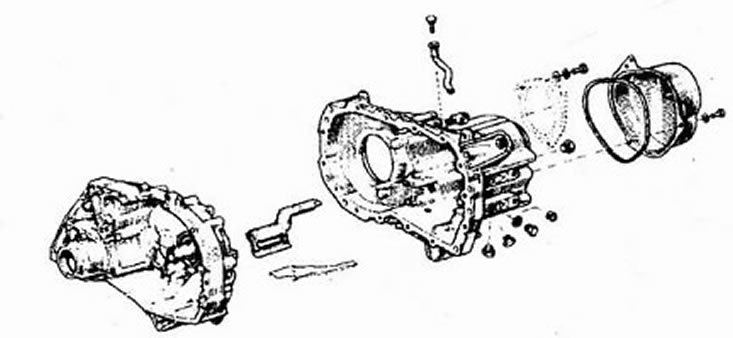
Crankcases and gearbox covers
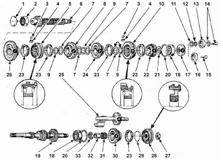
Gearbox gears. 1 - Oil deflector, 2 - Roller bearing, 3 - Roller, 4 - Roller spring, 5 - 1st gear, b - Output shaft, 7 - Slotted washer, 8 - Second gear, 9 - Retaining ring, 10 - 3rd and 4th gear hub and sliding sleeve, 11 - Washer, 12 - 5th gear retaining ring, 13 - Flanged washer, 14 - Stop bolt and washer, 15 - 5th gear tip located on output shaft, 16 - Support washer, 17 - 5th gear (secondary shaft), 18 - Ball bearing, 19 - Input shaft, 20 - Retaining ring, 21 - Washer, 22 - 4th gear, 23 - Synchronizer ring, 24 - 3rd gear, 25 - Reverse gear assembly with axle, 26 - 1st gear, 27 - 5th gear nut, 28 - 5th gear hub and sliding sleeve, 29 - 5th gear bushing, 30 - 5th gear (input shaft), 31 - Needle bearing, 32 - 5th gear bushing, 33 - Washer.
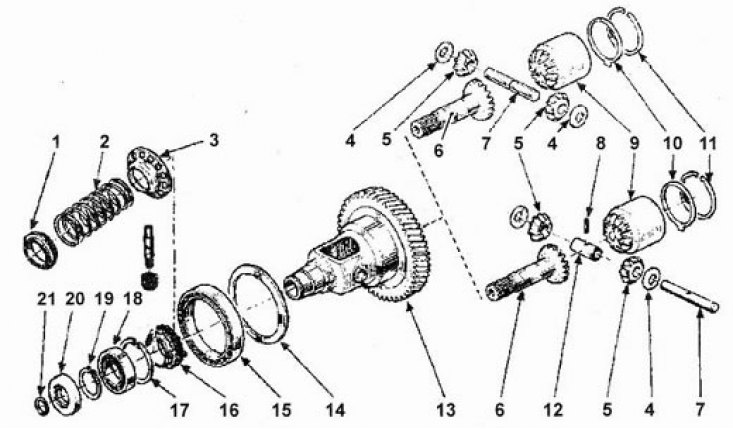
Differential made on ball bearings. 1 - Support washer, 2 - Spring, 3 - Speedometer sensor ring gear, 4 - Planetary washers, 5 - Planetary gears, 6 - Side gear with shank, 7 - Pinion axle, 8 - Elastic pin, 9 - Three-pin joint side gear, 10 - Gasket thickness, 11 - snap ring, 12 - Spacer, 13 - Differential, 14 - Spring washer, 15 - Ball bearing, 16 - Speedometer drive gear, 17 - Bearing circlip, 18 - Ball bearing, 19 - Retaining side gear ring with shank, 20 - O-ring, 21 - O-ring.
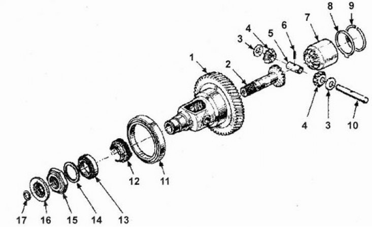
Differential made on roller bearings. 1 - Differential, 2 - Side gear with shank, 3 - Planetary washers, 4 - Planetary gears, 5 - Spacer, 6 - Resilient pin, 7 - Three-pin joint side gear, 8 - Gasket thickness, 9 - Snap ring, 10 - Pinion axle, 11 - Tapered bearing, 12 - Speedometer drive gear, 13 - Tapered bearing, 14 - Adjusting washer, 15 - Differential nut, 16 - Seal, 17 - O-ring.
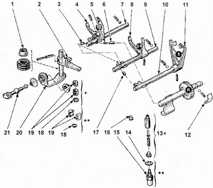
Gear change mechanism. 1 - Sealing sleeve, 2 - Gearshift lever, 3 - Rod lock key 1st and 2nd gears, 3rd and 4th gears, 4 - Shift fork, 5 - Rod lock key 1st and 2- 1st and 2nd gear, 6 - 1st and 2nd gear and reverse rod locking pin, 7 - 1st and 2nd gear rod, 8 - 3rd and 4th shift fork, 9 - 3rd gear rod her and 4th gear, 10 - Stem 5th gear (five-speed gearbox), 11 - 5th gear selector fork (five-speed gearbox), 12 - U-shaped reverse lock holder, 13 - 5th gear stop (five-speed gearbox), 14 - 5th gear stop adjusting washer, 15 - 5th gear stop (five-speed gearbox), 16 - Threaded stop, 17 - 5th gear lock key (five-speed gearbox), 18 - Retaining ring, 19 - Traction support, 20 - Input shaft, 21 - Traction.
The gearbox is installed in the engine compartment transversely to the longitudinal axis of the engine and bolted to it. This arrangement has the advantage of providing the shortest (possible) transmission path to the front wheels. It also optimizes cooling by positioning the gearbox in the air flow through the engine compartment.
Torque from the crankshaft through the clutch is transmitted to the input shaft of the gearbox.
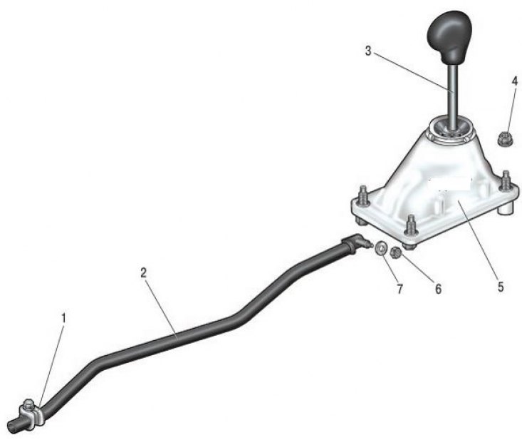
Manual transmission control drive: 1 - a collar of fastening of draft of a drive of management of a transmission; 2 - thrust of the gearbox control drive; 3 - gearbox control lever; 4, 6 - nuts; 5 - linkage of the gearbox control lever; 7 - washer
The gearshift drive is designed to control the gearbox by the driver from the car.
Gear selection is carried out using a gear lever mounted on the floor of the passenger compartment, which is connected to the gearbox by a gear shift rod. The link actuates a series of forks located inside the gearbox, which are installed in the cutouts of the synchronizer sliding sleeves. The clutches are locked onto the gearbox shafts, but can slide axially over them due to the presence of ground hubs that press against the blocking rings, bringing them into contact with the corresponding gears. The conical surface of the blocking ring and gear acts as a friction clutch, which gradually equalizes the speed of the synchronizer sliding clutch (and, consequently, the gearbox shaft) and gear speed. The blocking pin, which is included in the figured cutout of the blocking ring, prevents the engagement of the synchronizer clutch ring with the gear until their speeds become equal. This ensures smooth shifting and reduces noise and wear caused by fast gear shifts. Torque is transmitted to the driven gear of the final drive, which transmits rotation through the pinions of the planetary gear to the differential gears and drive shafts. The rotation of the satellites on their axes allows the inner wheel of the car to rotate at a lower speed when cornering than the outer one. The main gear and differential are installed in the same crankcase in such a way that the disassembly of one unit inevitably leads to a malfunction of the other unit. Adjustment and repair of the main gear require the use of a number of special tools and devices.