
Attention! This subsection describes the removal of the gearbox as a separate unit with its separation from the engine installed on the vehicle.
Special tool:
- Punch set for removing guide pins - B.Vi. 31-01
- Subframe support - Mot. 1040-01
- Ball joint puller - T.Av. 476
- Drain plug - - - 22 Nm
- Drive shaft boot bolt - 25 Nm
- Lower ball joint nut - 65 Nm
- Shock absorber support bolt - 180 Nm
- Starter bolt - 45 Nm
- Gearbox support bolt - 62 Nm
- Wheel bolt - 90 Nm
- Steering shaft joint bolt - 30 Nm
- Rear subframe bolt - 105 Nm
- Front subframe bolt - 62 Nm
- Tie rod ball joint nut - 40 Nm
- Engine tie rod bolt - 65 Nm
Removing
- install the car on a lift or overpass;
- remove the protective cover of the power unit;
- disconnect the wire from the negative terminal of the battery;
- disconnect the connectors from the ECU and the impact fuel switch, move the wires away from the work area and secure them;
- remove the air intake pipe of the air filter;
- dismantle the battery tray;
- disconnect the clutch cable from the gearbox and move it to the side;
- unscrew the two bolts and remove the crankshaft position sensor located at the top in the flywheel area;
- disconnect «massive» tires from the gearbox housing;
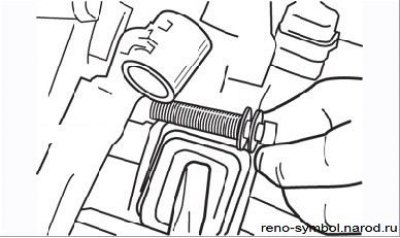
Do not completely unscrew the top gearbox-to-engine bolt - remove the gearbox-to-engine block bolts, but leave the top bolt hand-tight until the gearbox is removed (Figure 4.15);
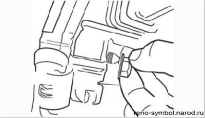
Lower front nut securing gearbox to engine - unscrew and remove the front lower nut securing gearbox to engine, remembering the installation of the wiring bracket (Figure 4.16);
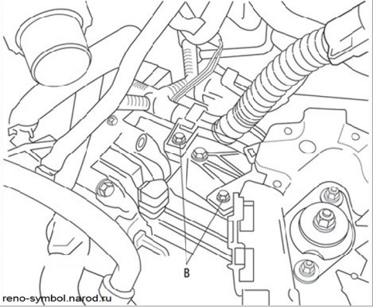
bolts (IN) gearbox mounts:
- unscrew the two bolts of the supporting brackets B
- remove the front wheels;
- remove the right front wheel drive shaft (see subsection «Front wheel drive»);
- remove the left front wheel drive shaft together with the wheel hub (see subsection «Front wheel drive»);
- remove the starter (see section «electrical equipment»);
- disconnect the connectors of the reverse light switch and the speedometer sensor, remove the speedometer sensor;
- remove a reception pipe of system of release of the fulfilled gases;
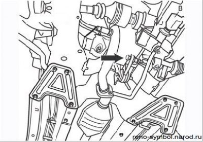
Figure 4.18. Bolt (IN) gearshift linkage (under the cover) and a bolt of fastening of a back support of a transmission (arrow)
- remove the gearshift linkage assembly by unscrewing bolt B (Figure 4.18) and three bolts securing the heat shield, to gain access to the support of the gear lever;
- remove the jet thrust bolt;
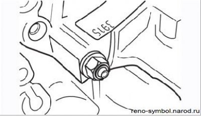
Figure 4.19. Fastening of a back support of a transmission
- remove the rear gearbox mount (Figure 4.19);
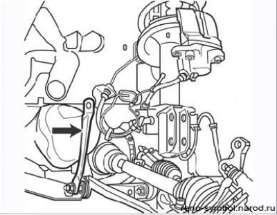
Figure 4.20. Connecting tag (arrow) between subframe and body
- remove the connecting rod subframe and body (Figure 4.20) From the left side;
- remove the tie between the engine and gearbox;
- unscrew the bolts securing the steering mechanism to the subframe, as described in section «Steering»;
- to facilitate the removal of the steering mechanism, if necessary, install a lining between the rear wall of the engine and the engine shield to tilt the engine forward;
- disconnect the steering mechanism and remove it, fix it to the side;
- using a lifting device, hang out the power unit;
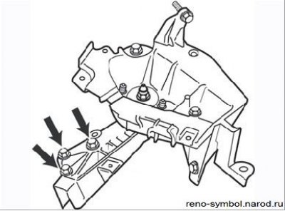
Figure 4.21. three bolts (arrows) fastening of the support on the gearbox housing
- unscrew the three bolts securing the support on the gearbox housing (Figure 4.21);
- lower the power unit as far as possible without damaging the cooling system hoses;
- support the subframe with a rolling jack, placing a piece of board on the head of the jack, unscrew the four fastening bolts and lower the subframe to the floor;
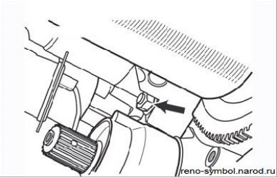
Figure 4.22. Loosen the remaining transmission-to-engine mount
- place a rolling jack under the gearbox, unscrew the remaining upper mount of the gearbox to the engine (Figure 4.22) and together with an assistant, remove the gearbox from under the car.
Installation
1. Lubricate the fork pads and release bearing guide with MOLYCOTE BR2 grease.
2. Insert the fork into the notches of the release bearing.
3. Check the spelling and correct installation of the gearbox centering rings
4. Connect the gearbox to the engine. Do not allow the motor position to change.
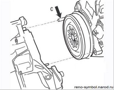
Figure 4.23. Installing an additional stud (arrow) when connecting the gearbox to the engine
5. To facilitate the installation of the gearbox, use a guide pin (WITH).
6. Install:
- stretcher:
- steering gear;
- exhaust pipe:
- subframe connecting rod;
- when attaching the front wheel drive shafts to the box, install new spring pins and seal them with sealant;
- check the oil level in the box and take a test drive.