
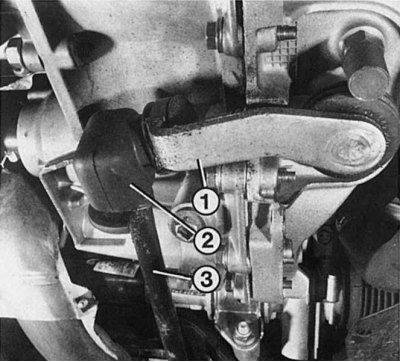
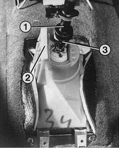
Mounting control rod (3) in the shift lever (1) gearbox, it is necessary to check the integrity of the sealing cuff (2). There should be some grease in the sealing collar so that the screw pin and bushing do not fail prematurely. A worn joint causes inaccurate gear shifting and cannot be adjusted.
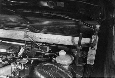
Since the engine rests on the gearbox, it must be suspended in order to remove the gearbox. The workshop uses a special suspension device with a screw collar for this purpose, with which it is possible to center the engine with millimeter accuracy - this is especially important during assembly. You can do it the way it is shown in the picture. It is important that when hanging, the strength of the materials used is sufficient, as well as to protect the engine from slipping. For example, you can strengthen the cross member with clamps on the body.
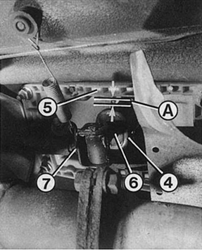
If 1st gear is engaged, then the shift lever (1 and 6) when properly adjusted, it must rest against the top reverse lock (3) to the top limiter (2) gearboxes. Simultaneously between the lower reversing blocker (4) and lower limiter (5) there should be a gap «A», equal to 2 mm. If this is not the case, then the gearshift mechanism needs to be adjusted. Numeric «7» the control rod fork is indicated, in which, in the 1st gear position, when the rod is tightened, there should be a distance of 5 mm from the end of the rod to the start of rolling.
 |  |
Removing
1. Disconnect the wires from the battery terminals and remove it.
2. If necessary, remove the engine hood to increase working space.
3. Remove the air filter housing with mounting.
4. Disconnect the clutch cable from the gearbox.
5. Remove the tachometer shaft from the gearbox.
6. Disconnect the plug connection of the reversing light switch.
7. Disconnect a wire of weight from a transmission.
8. Disconnect wires from a starter, at the same time mark sockets in advance.
9. Drain gear oil into a container.
10. Petrol vehicle only: Remove the RPM sensor.
11. Disconnect the connectors for the radiator fan and thermostat.
12. Turn off the top fastening of a radiator and shift a radiator carefully to the right side. To protect the radiator plates, cover them with cardboard.
13. Diesel only: Drain the coolant into a clean container. To do this, remove the lower radiator hose.
14. Remove a radiator together with the fan.
15. All engines: Raise the front of the vehicle, chock and remove the wheels.
16. Left side of vehicle: Completely remove disc brake calipers and tie wire to fender.
17. Remove mud flaps.
18. Wring out draft of a steering trapeze from a steering rotary support.
19. Remove the power shaft seal from the gearbox.
20. Remove the bottom fastening of a rack of the shock-absorber from a rotary fist.
21. Remove the spherical ball pin of the cross balancer from the steering knuckle.
22. Press the transverse balancer down from the steering knuckle (using the mount).
23. Remove the drive shaft completely with the steering knuckle and brake disc so that the bearing rollers of the inner joint do not fall into the gearbox housing.
24. When disassembling the shaft, avoid excessive stress on the joints due to stretching. The bending angle of the inner and outer hinges must not be exceeded.
25. Right side of vehicle: Use a suitable drift to drive the driveshaft spacer pin out of the gearbox.
26. Remove the lower shock absorber mount from the steering knuckle (2 bolts with nut).
27. Pull the steering knuckle out and move it to the side until the drive shaft comes out of the gearbox.
28. Unscrew the bracket connecting the box to the engine from the gearbox.
29. Remove both lower connecting bolts between engine and transmission.
30. Remove the transmission mudguard.
31. Pull back the boot from the transmission control rod and remove it.
32. Tie the control rod to the exhaust pipe with wire.
33. Secure the engine with a hoist.
34. Turn off connecting bolts of a transmission/starter and remove a starter.
35. Fix the gearbox from below with a car jack, without loading it too much.
36. Unscrew the bolts of the front and rear mounting between the engine and gearbox (from gearbox and bearing) and take them out.
37. Diesel only: remove balancer from gearbox (3 bolts in gearbox, 4 bolts in stringer).
38. Remove the bottom (reaction torque lever) torque support. Note the order in which the screws are mounted!
39. All motors: Install the locknuts on the left and right spacer bolts and tighten. To unscrew the spacer bolts, you need an angled box wrench, as well as an articulated wrench.
40. If necessary remove both collars of a hose of the servo-drive of the steering mechanism.
41. Carefully pry the gearbox out of the engine housing with a pry bar. At the same time, install the gearbox with a side cover (there are 5th gears) between the spar and the auxiliary frame.
42. Raise the engine slightly.
43. To prevent the clutch release bearing from slipping off the drive shaft, it is necessary to fix the clutch release fork with a suitable plate inserted between the fork and the clutch cable support.
44. If an optional hoist is available, secure the chain to the gearbox flange bolts and clutch cable support.
45. Lower the gearbox to the side of the gearbox cover.
46. Using a lifting mechanism or an assistant, carefully remove the gearbox from the engine compartment.
Installation
1. Before installation, lubricate the input shaft of the gearbox and the guide sleeve of the thrust bearing with a thin layer of paste «Molykote 55 Plus».
2. Lubricate the wedge engagement of the drive and driveshafts with a small amount of MoS2 grease.
3. Check the correct location of the centering sleeves in the gearbox flange.
4. Lower the gearbox into the engine compartment and align it with the engine.
5. Tighten the spacer bolts.
6. Install the connecting bolts and tighten (M 10 torque 45 Nm; M12 torque 55 Nm).
7. Check the position of the engine-gearbox system in the engine compartment and, if necessary, correct it.
8. Installation is carried out in the reverse order to removing the gearbox.
9. If necessary, adjust gear shifting.
Note. Recommendation: Excess lubricant on the gearbox input shaft can get on the clutch disc. Therefore, apply it in small amounts.
The gearbox housing is made of light metal. Overtightening threaded connections can cause thread stripping. It is therefore very important that the specified tightening torques for all bolts are observed.