



Attention! If a new torque converter or gearbox is to be installed, reprogram the ECU using the XR25 tester.
Do not remove the transmission from the vehicle for the intended repair until a professional diagnosis has been made, as many checks can only be performed with the transmission installed in the vehicle.
Removal procedure:
- place the car on a lift;
- remove the battery and its tray;
- remove the protective cover of the power unit;
- remove the front wheels;
- remove the air filter housing and intake duct;
- disconnect the selector cable ball joint from the multifunction switch;
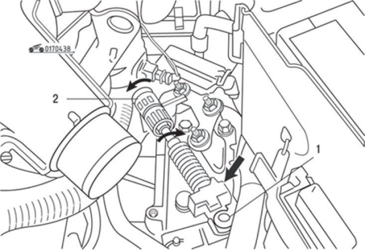
Fig. 4.38. Disconnecting the ball end (1) of the selector cable and turning the locking rings (2) of the cable sheath in different directions (the arrow shows the moving part of the hydraulic distributor)
- remove the outer casing of the selector cable by turning the two locking rings in opposite directions (Fig. 4.38);
Note: Do not move the orange ring during this operation. It may break during removal or installation. If this happens, do not replace the selector cable, as the absence of the ring does not affect the operation of the system.
The text is available on this website (renaultbook.ru)
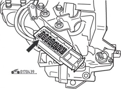
Fig. 4.39. Gearbox modular connector (arrow)
- disconnect the modular connector (Fig. 4.39), releasing its wiring.
Protect the connector from damage by packing it in a waterproof plastic bag;
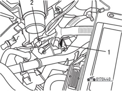
Fig. 4.40. Wiring harness (1) mounting bracket, TDC sensor (2)
- unscrew the wire harness bracket bolts and remove it (Fig. 4.40);
- remove the TDC sensor from the engine;
- install clamps on the hoses on both sides of the oil cooler and disconnect it;
- disconnect the connector from the exhaust gas oxygen sensor;
- disconnect both front wheel drive shafts from the gearbox as described in the subsection "Front wheel drive shafts";
- unscrew the bolts and nuts securing the steering gear to the subframe, secure it so that it does not interfere with the work; take care not to damage the power steering lines;
- disconnect the input and output speed sensor connectors;
- remove the starter (see section "Electrical equipment");
- remove the intake pipe of the exhaust system;
- disconnect the thrust rod from the gearbox;
- unscrew the bolts and remove the ground busbars from the gearbox;
- transfer the weight of the subframe to the trolley jack;
- connect the hoist to the engine lifting eyes and lift it up;
- tie the radiator of the cooling system to the front cross member of the engine compartment, unscrew the subframe mounting bolts and lower it;
- remove the rear gearbox support;
- the torque converter is bolted to the faceplate with three nuts, which can be accessed through the starter hole. Turn the crankshaft clockwise until the nuts become visible through the starter hole one by one, unscrew and remove them;
Attention! Nuts must be replaced after unscrewing.
- transfer the weight of the gearbox to a trolley jack or (which is preferable) on a special stand for the gearbox;
- remove the left engine mount;
- lower the transmission and engine as much as possible, being careful not to damage the air conditioning compressor;
- transferring the weight of the gearbox to the trolley jack, loosening, unscrew the bolts and unscrew the nuts securing the gearbox to the engine, remember the location of all nuts, bolts and brackets for correct subsequent installation. Check again whether everything is disconnected and moved to the sides so that the gearbox can be removed without interference;
- disconnect the automatic transmission from the engine, being careful not to dislodge the torque converter;
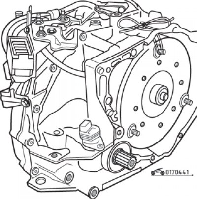
Fig. 4.41. Fixing the torque converter with a cord to prevent it from shifting
- after moving the box away, lower the jack and remove the box from under the car. If the guide bushings have a weak fit, remove them and fold them so that they do not get lost. Secure the torque converter by tying it to the gearbox housing through the hole for the TDC sensor in the clutch housing (Fig. 4.41).
Installation procedure:
- untie the torque converter and align it with the gearbox. Apply a layer of Molykote BR2 molybdenum grease to the torque converter centering ring;
- install the guide bushings in their places and clean the threads of the torque converter mounting posts to the faceplate;
- when installing the transmission, align the torque converter threaded posts with the holes in the faceplate. Apply Loctite Frenbloc anaerobic sealant to the threads of the new nuts, screw them on and tighten them to the specified torque;
- connect the selector cable and adjust it as described below;
- perform the remaining operations in the reverse order of removal;
- finally, add the required amount of fluid of the prescribed type to the box as described above.