



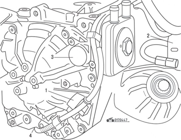
Fig. 4.47. Location of sensors on the gearbox: 1 – torque converter turbine speed sensor; 2 – speed sensor; 3 – electromagnetic valve for regulating the cooler capacity; 4 – pressure sensor in the pressure line
The following sensors are installed on the automatic transmission (Fig. 4.47):
- torque converter turbine speed sensor 1;
- sensor 2 speed of movement;
- electromagnetic valve 3 for regulating the cooler capacity;
- pressure sensor 4 in the pressure line.
Removal of the rotation speed sensors, pressure sensor in the discharge line and electromagnetic valve for regulating the cooler capacity is performed without draining the oil and removing the automatic transmission.
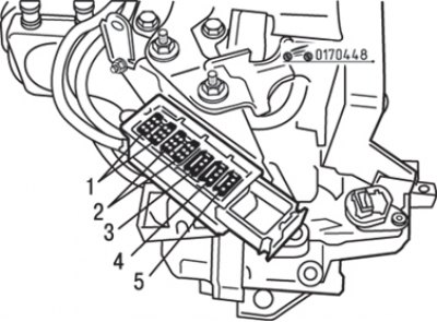
Fig. 4.48. Modular connector: 1 - green color (multi-function switch); 2 - yellow (electronic hydraulic system interface); 3 - green color (line pressure); 4 - yellow (turbine speed); 5 - blue (car speed)
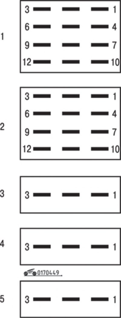
Fig. 4.49. Modular connector pin numbering
When replacing a sensor, always replace the modular connector (Fig. 4.48). The numbering of the modular connector contacts is shown in Fig. 4.49.
Text published on the website: Renaultbook.ru