
Note. Renault recommends lowering the engine together with the transmission from the engine compartment.
Removing
1. Disconnect the ground cable from the battery (contact the head Engine electrical equipment).
Attention! If the car radio in your car is coded, make sure you know the code before disconnecting the battery.
2. Remove a radiator as it is described in the Head Cooling, heating system.
3. Drain the transmission fluid as described in Chapter Maintenance.
4. If necessary, drain the engine oil.
5. Remove a cowl as it is described in the Head Body.
6. Engage the handbrake, then jack up the front of the vehicle and place it on axle stands. Remove both front wheels. Where available, remove the lower engine cover.
7. Remove liners of arches of forward wheels.
8. Turn away cores fastening a stretcher to a body, from each party of the car.
9. Turn away supports of a forward brake from rotary fists as it is described in the Head Brake system, and tie them to the body.
10. On models with ABS, unscrew the wheel speed sensors and remove them from the steering knuckles.
11. Remove a forward bumper as it is described in the Head Body.
12. Remove the downpipe and the catalytic converter, proceeding according to the description in the Chapter Power and exhaust systems.
13. Remove the sound signal as described in Chapter Onboard electrical equipment.
14. Remove the air filter assembly as described in Chapter Power and exhaust systems.
15. Turn away a cable of weight from a bulkhead.
16. Disconnect a hose of the gauge of pressure in the pipeline from the inlet pipeline and disconnect electroconducting from the gauge.
17. Remove expansion tank and attach to engine/transmission assembly.
18. Disconnect the gas pedal cable from the throttle body.
19. Disconnect the wiring from the downshift mechanism.
20. Disconnect a hose of the block of the vacuum amplifier of brakes from the inlet pipeline.
21. Remove the top and side covers from the relay box on the left side of the engine compartment, then release the relay board and wiring ties and move the wiring to the engine.
22. Disconnect the electrical wiring from the automatic transmission control unit on the left side of the engine compartment.
23. Disconnect the charcoal canister hose from the solenoid valve on the intake manifold.
24. Disconnect the starter power cable from the battery. To do this, remove the battery (Chapter Engine electrical equipment) and disconnect the wiring, then release the cable from the cover/o-ring in the bulkhead panel of the engine room. Also disconnect the supply wire of the fuel injection system.
25. Loosen the brackets and disconnect the supply and return fuel hoses from the fuel line.
26. Disconnect the heater hoses from the thermostat housing.
27. Disconnect the gear selector control from the transmission (contact the head Transmission).
28. Remove auxiliary drive belt (contact the head Maintenance).
29. Remove the pulley from the power steering pump as described in Chapter Suspension and steering.
30. Remove the three power steering pump mounting bolts and, where applicable, the four air conditioning compressor mounting bolts. Move the pump and compressor to the side, but do not disconnect the pipes.
31. Release the air conditioning low pressure pipe from the lower engine/transmission mount.
32. Remove the left engine/transmission mount. But first insert a wooden wedge between the transmission and the left side of the subframe to support the weight of the transmission. On K7M engines, loosen the lower mounting nut from the subframe and the upper mounting nut from the bracket. On F3R engines, remove the nut from the top of the strut, then use a mallet to knock out the thru-strut.
33. Remove the right engine/transmission bracket.
34. Attach the winch to the mounting lugs and slightly raise the engine.
35. Turn away (but don't shoot) nut from the rear engine/transmission rear mount coupler, then loosen and remove the front coupler bolt. Unbolt the rear support bracket from the transmission.
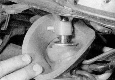
36. Set the front wheels to position "directly". Working in the engine compartment, slide the rubber sealing ring back, then unscrew the eccentric bolt that secures the steering column base to the steering mechanism, and separate the steering column (contact the head Suspension and steering) (refer to accompanying illustration).
Attention! On models with an airbag, it is important not to damage the airbag sliding contact below the steering wheel. Before removing the steering column, the steering wheel must be locked with a special tool.
37. Turn away four bolts of fastening of a stretcher to the bottom in corners so that it lowered on 10 mm.
38. Loosen the bolts securing the two reinforcing brackets to the bottom.
39. Turn away as far as possible fixing bolts of the steering mechanism. The two reinforcing brackets must be left in place.
40. Remove the bolts and heat shields from the bottom of the shift lever, then unhook the return spring from the shift rod.
41. Turn the stem back and secure it in this position.
42. Remove the speed / crankshaft position sensor, disconnect the wiring and release it from the subframe.
43. Prepare a dolly with wooden blocks to support the subframe and check that the engine/transmission assembly is supported securely. Renault mechanics use a special trolley (Mot. 1040-01) and supporting tools Mot. 1159 and Mot. 1159-02.
44. Turn away bolts of fastening of a stretcher to the bottom, noticing a location of spacers and washers. Don't forget to remove the bolts securing the power steering tube to the subframe.
45. Turn away bolts of the top fastening of a rack of a forward suspension bracket from towers.
46. Raise the car body, then release the handbrake and move the car back. Then lower the vehicle to the ground and apply the handbrake.
47. Have an assistant move the lower parts of the suspension struts outward while releasing the drive shafts from the transmission. Tie up the drive shafts.
48. Check again that all components that may interfere with the removal of the engine / transmission assembly have been removed or disconnected. Remove the assembly from the subframe.
Installation
1. Install in reverse order, tighten all nuts and bolts to the torque given in the Specifications. When fixing the subframe to the bottom, screw 100 mm rods into the nuts to adjust the position of the bolt holes. With the front of the subframe aligned, insert the rear bolts, then unscrew the rods and insert the front bolts. At connection of a steering column with the steering mechanism be guided by the Head Suspension and steering. Top up the fluid level in the power steering hydraulic system. Fill the engine with oil and the cooling system with coolant as described in Chapter Maintenance. Fill the automatic transmission as described in Chapter Transmission. Before performing a test drive, depress the brake pedal several times until the brake pads return to their normal position.