
Cleaning
1. Remove all traces of the old gasket from the cylinder head.
2. Clean the combustion chambers and bores of carbon deposits, then thoroughly flush the cylinder head with kerosene or a suitable solvent.
3. Scrape most of the carbon off the valves, then use a wire brush to remove any remaining carbon from the valve heads and stems.
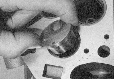
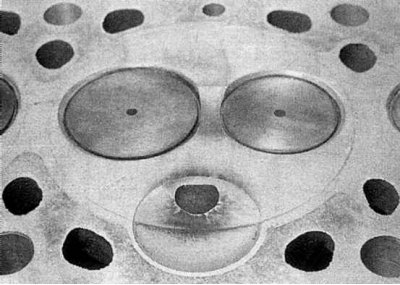
4. On F8Q engines, swirl chambers must be removed if they are loose (mark the location of the cameras so that they can be installed in the same place) (refer to accompanying illustration).
5. If the head is extremely dirty, it must be cleaned with steam. Finally, make sure that all lubrication holes and lubrication channels are clear.
Note. Perform all inspection procedures before concluding that it is necessary to go to an auto repair shop for regrinding. Make a list of all components that require processing.
Inspection and maintenance
Cylinder head
1. Carefully inspect the head for cracks, other damage, and coolant leaks. If cracks are found, replace the head.
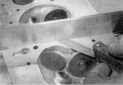
2a. Using a straight edge and a feeler gauge, check the surface of the cylinder head for deformation. On F8Q engines, make sure that the edge of the ruler does not pass over the swirl chambers, as they may protrude above the seating surface of the cylinder head. If the deformation exceeds the limit specified in the Specifications, the manufacturer does not recommend grinding the surface, and the only way out is to replace the cylinder head.
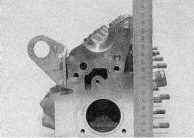
2b. Check that the total height of the cylinder head corresponds to the value specified in the Specifications (refer to illustrations).
3. Inspect all valve seats. If they are severely pitted, cracked, or burnt, have a professional resharpen them. If pitting is minor, it can be removed by grinding the valve head and seat with a special fine paste as described below. Note that on diesel engines, valve seats can only be ground to a limited depth to avoid compression loss. Using a micrometer, verify that the valve depth is below the cylinder head seating surface within the limits provided in the Specifications in Part C of this Chapter (refer to accompanying illustration).
4. If the valve guides are worn (valve moves horizontally), replace the guides. A micrometer can be used to determine valve lateral movement. Install a new valve in the guide and check its side play to determine if the valve or the guide itself is worn. If new guides need to be installed, the valves must also be replaced. It is better to entrust this work to a specialist, since if it is done skillfully, there is a risk of damage to the cylinder head.
5a. On F8Q engines, inspect the condition of the swirl chambers for burnt spots or cracks. If required, the chambers can be replaced.
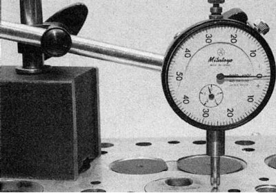
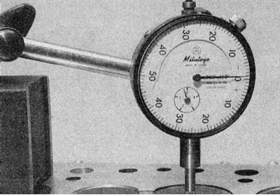
5b. Using a micrometer, check that the swirl chambers do not protrude from the head more than specified in the Specifications. Zero the micrometer on the surface of the cylinder head, then measure the protrusion of the swirl chamber (refer to illustrations).
6. Where applicable, check the tappet seats in the cylinder head for signs of wear. If there is excessive wear, the cylinder head must be replaced.
7. Inspect the running surfaces of the camshaft bearings in the cylinder head (and caps/bearing fasteners, where applicable). If worn, the head must be replaced.
Valves
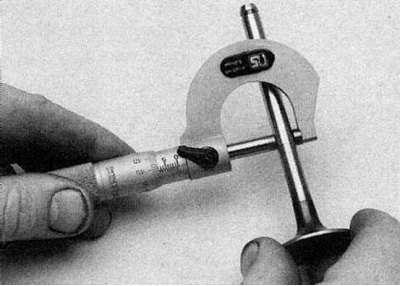
1. Inspect each valve head for pitting, burn spots, cracks, and signs of general wear. Check the valve stem for scratches and gouges.
Rotate the valve and inspect it for signs of deformation. Inspect the end of each stem for pitting and signs of excessive wear. If the condition of the valve seems to be satisfactory, measure the stem diameter in several places with a micrometer (refer to accompanying illustration). Any significant difference in the data obtained indicates wear on the valve stem, which means the valve must be replaced. If the valves are not damaged, they should be lapped to ensure a tight fit to the seats.
2. Lapping of valves is performed as follows. Turn the cylinder head upside down with a block of wood under each end to provide clearance for the valve stems.
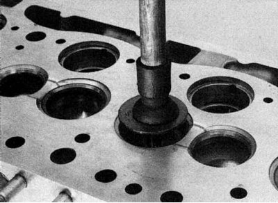
3. Apply an appropriate grade of lapping paste to the valve seat surface and attach the special suction cup to the valve head. Rotating the valve back and forth half a turn, grind its head, lapping it against the seat, occasionally lifting the valve to redistribute the paste (refer to accompanying illustration). Installing a weak spring under the valve head will greatly facilitate the work. If a coarse grinding paste is used, work until the seat and valve contact surfaces are dull, then wipe off the compound and repeat the process with a fine paste. When the seat and valve surfaces are a uniform light gray color, lapping is complete. Do not lap the valves longer than necessary, as this will cause the seat to dig into the cylinder head undesirably. When all valves are lapped, carefully wash off all traces of grinding paste using kerosene or a suitable solvent.
Valve components
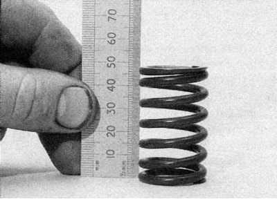
1. Inspect the valve springs for signs of damage and discoloration, and measure their free length with a ruler (refer to accompanying illustration), or compare with a new spring.
2. Place each spring on a flat surface and check for deformation with a square. If any of the springs are damaged, distorted, or loose, purchase a new complete set of springs. It is recommended that the springs be replaced each time they are removed during an engine overhaul, regardless of their condition.
3. Where applicable, check tappets and shims for scratches, corrosion (especially on pucks) and wear. Replace all components as needed.
Rocker Arm Components - E7J and K7M Engines
1. Check the contact surfaces of the rocker arms for pits, scratches, or other signs of wear. Disassemble the rocker shaft and check the rocker arms, pivot shafts and contact surfaces in the same way. Measure the inside diameter of each rocker and check for placement on the shaft. Clean the oil passages in each rocker using a piece of wire. Replace rocker arms or axles if necessary.
Oil seals
1. Oil seals should be replaced after each removal.