
Models with engines 1.4 and 1.6 l
Note. The engine along with the gearbox is removed from the engine compartment upwards, and then they are separated.
Removing
1. Disconnect the ground cable from the battery.
Attention! If the car radio in your car is coded, make sure you know the code before disconnecting the battery.
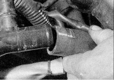
2. Remove a radiator as it is described in the Head Cooling, heating system. Also disconnect the top hose from the thermostat housing and the bottom hose from the coolant pipe (refer to accompanying illustration).
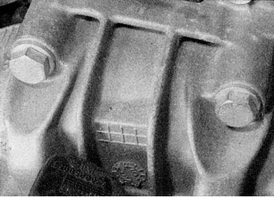
3. Drain transmission oil as described in Chapter Transmission (refer to accompanying illustration).
4. If necessary, drain the engine oil as described in Chapter Maintenance.
5. Remove a cowl as it is described in the Head Body.
6. Where applicable, remove the reinforcing rod between the front suspension strut domes.
7. Remove the air filter assembly as described in Chapter Power systems, release.
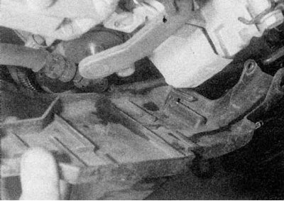
8. Engage the handbrake, then jack up the front of the vehicle and place it on axle stands. Remove the front wheels and wheel arch liners. Where available, remove the lower engine cover.
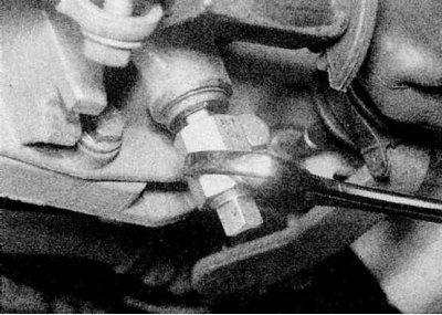
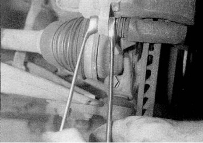
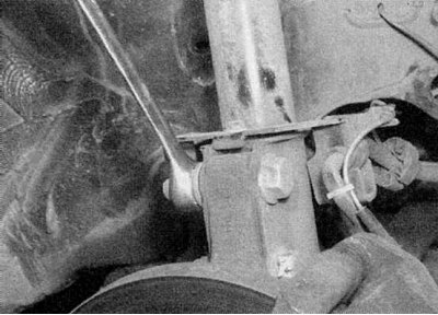
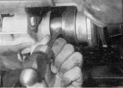
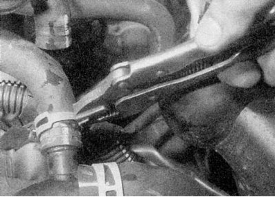
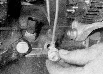
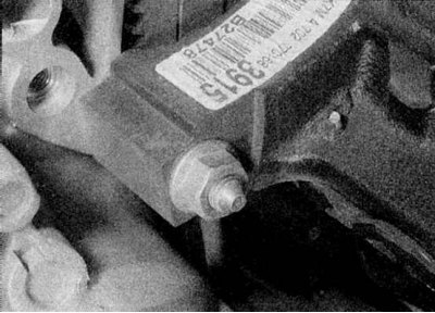
9. Remove the nut from the left tie rod end and disconnect it from the steering knuckle arm (refer to accompanying illustration).
10. Remove the three bolts securing the left driveshaft inner rubber boot and metal ring to the transmission.
11a. Remove the two mounting bolts securing the left brake caliper to the steering knuckle.
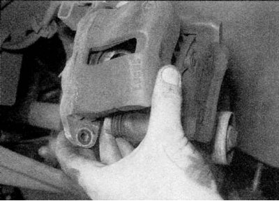
11b. Remove the left brake caliper.
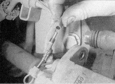
11c. Disconnect the wiring harness from the pad wear sensor. Tie the caliper to the suspension spring (refer to illustrations).
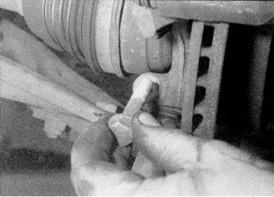
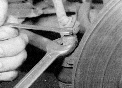
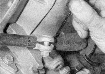
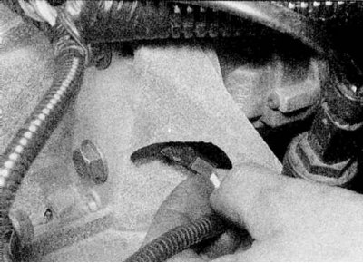
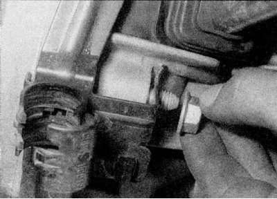
12. Unscrew and remove the pinch bolt securing the ball joint of the left lower arm to the steering knuckle (refer to accompanying illustration).
13a. Loosen the nuts (note that the nuts are on the back of the shroud).
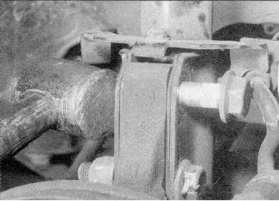
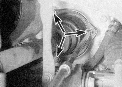
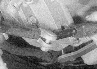
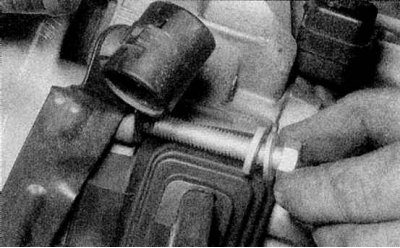
13b. Loosen and remove both bolts securing the left suspension strut to the steering knuckle (refer to illustrations).
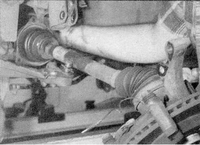
14. Lower the lower suspension arm down, then separate the drive shaft from the differential drive wheel and remove it together with the steering knuckle (refer to accompanying illustration).
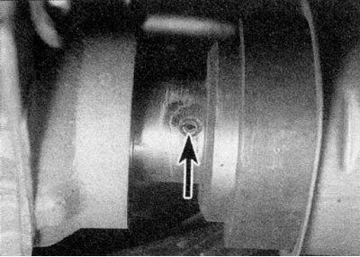
15a. A pin that secures the right drive shaft to the differential drive wheel shaft.
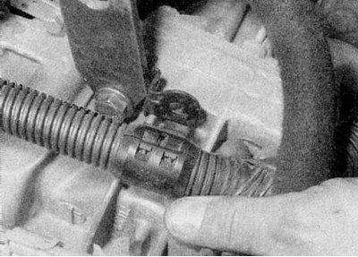
15b. Working under the vehicle, knock out the pin (refer to illustrations).
16. Remove the nut from the right tie rod end and disconnect it from the steering knuckle arm.
17. Unscrew and remove the upper bolt securing the right suspension strut to the steering knuckle (note that the nut is on the back). then loosen (but don't shoot) bottom bolt.
18. Pull the drive shaft towards you and disconnect its inner end from the grooves on the differential drive wheel shaft. Tie the drive shaft to the steering gear.
19. Remove a reception pipe and the catalytic converter as it is described in the Head Power and exhaust systems.
20a. Loosen the screws and remove the plastic cover from the transmission base.
20b. Then mark the position of the selector rod on the fork in the transmission.
20s. Then loosen the pinch bolt and split the stem (refer to illustrations).
21. Where available, separate the power steering hydraulic tubes from the transmission.
22a. Pull out the spring clip.
22b. Remove the vehicle speed sensor from the rear of the transmission (refer to illustrations).
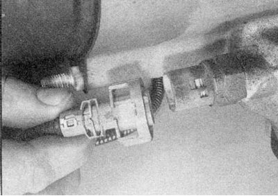
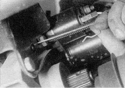
23. Disconnect the wiring from the reversing light switch on the transmission (refer to accompanying illustration).
24. On models without an air conditioner, remove the pump and power steering reservoir from the engine as described in Chapter Suspension and steering, but do not disconnect the hydraulic pipes. Move the pump to the side (refer to accompanying illustration).
25. On air-conditioned models, remove the power steering pump pulley and move the air conditioning pump and compressor to the side, leaving the hoses attached.
26. Disconnect the throttle cable from the throttle body (contact the head Power and exhaust systems).
27. Disconnect the clutch cable from the transmission as described in Chapter Clutch.
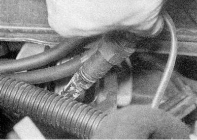
28. Disconnect remaining hoses from thermostat housing and/or coolant pipe (where available) on the left side of the engine (expansion tank hose and heater hoses) (refer to accompanying illustration).
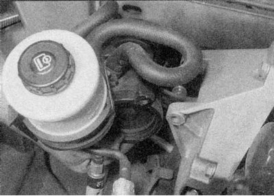
29. Unscrew the expansion tank and tie it to the left side of the engine compartment.
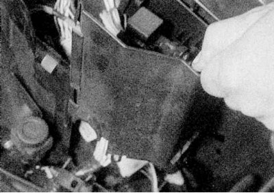
30a. Remove the top and side covers from the relay box on the left side of the engine compartment.
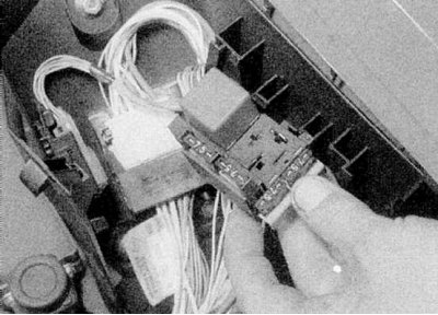
30b. Then release the relay board and wiring ties and place the wiring on the motor (refer to illustrations).
31. Disconnect wiring from radiator fan and thermal switch.
32. Disconnect the line pressure sensor hose from the intake manifold.
33. Disconnect the line pressure sensor hose from the intake manifold and disconnect the sensor wiring.
34. Turn away fixing nuts and remove the block of a control system of the engine from the right side of an impellent compartment. Tie the block to the top of the engine to prevent damage.
35. Loosen the clamps and disconnect the supply and return fuel hoses from the throttle body or fuel line.
36. Turn away a cable of weight from a bulkhead.
37. Disconnect the charcoal canister hose from the solenoid valve on the intake manifold.
38. Disconnect the wiring from the ignition amplifier block on the bulkhead or from the ignition coil on the cylinder head.
39. Disconnect the starter power cable from the battery. To do this, remove the battery (Chapter Engine electrical equipment) and disconnect the wiring in the connector block, then release the cable from the cover/o-ring in the bulkhead panel of the engine compartment. Also disconnect the supply wire of the fuel injection system. On Scenic models, unscrew the additional fuse box in the engine compartment and move it to the side.
40. Turn away nuts of the bottom forward fastening of the engine/transmission and remove a connecting plate from the right support.
41. Attach the winch to the engine mounting lugs and lift the engine slightly.
42. Remove the bracket bolts and coupler bolt from the rear engine/transmission mount. Lift the assembly slightly and remove the rear support bracket.
43. With the help of an assistant, slowly lift the engine/transmission assembly out of the engine compartment, being careful not to damage surrounding components. When the block is high enough, bring it forward and lower it to the floor.
44a. Disconnect wiring from starter.
44b. Disconnect the ground cable from the cylinder block.
44s. Disconnect the cable holder from the transmission.
44d. Loosen the front lower nut.
44e. Remove the upper transmission-to-engine bolt. Mark the position of the cable holder.
44f. Substitute the supports and unscrew the upper bolts securing the transmission to the engine.
44g. Loosen the nuts securing the transmission to the engine.
Models with 2.0L engines
Note. The engine, along with the gearbox, is lowered down from the engine compartment, and then they are separated.
Removing
1. Follow the preliminary steps described in paragraphs 1-23 above. Remove the left and right front wheel arch liners.
2. On models with air conditioning, disconnect the wiring from the pressure sensor and from the compressor.
3. Where applicable, disconnect the power steering pressure sensor.
4. Disconnect the throttle cable from the throttle body (contact the head Power and exhaust systems).
5. Disconnect the clutch cable from the transmission as described in Chapter Clutch.
6. Disconnect the heater hoses from the heater heat exchanger pipes on the bulkhead.
7. Disconnect the remaining hoses of the cooling system from the thermostat housing.
8. Disconnect the cooling system hoses and unscrew the expansion tank, then tie it to the left side of the engine compartment.
9. Remove the top and side covers from the relay box on the left side of the engine compartment, then release the relay board and wiring ties and place the wiring on the engine.
10. Disconnect wiring from radiator fan and thermal switch.
11. Disconnect a hose of the block of the vacuum amplifier of a brake from the inlet pipeline.
12. Disconnect the line pressure sensor hose from the intake manifold and disconnect the sensor wiring.
13. Turn away fixing nuts and remove the engine control unit from the right side of an impellent compartment. Tie the control box to the top of the engine.
14. Loosen the brackets and disconnect the supply and return fuel hoses from the fuel line. On F7R engines, release the tubes from the clips on the center outer toothed belt cover.
15. Turn away a cable of weight from a bulkhead.
16. Disconnect the charcoal canister hose from the solenoid valve on the intake manifold.
17. Disconnect the wiring from the ignition coils on the cylinder head.
18. Disconnect the starter power cable from the battery. To do this, remove the battery (Chapter Engine electrical equipment) and disconnect the wiring in the connector block, then release the cable from the cover/O-ring in the bulkhead panel of the engine compartment. Also disconnect the supply wire of the fuel injection system. On Scenic models, unscrew the additional fuse box in the engine compartment and move it to the side.
19. Remove the accessory belt.
20. Remove a pulley from the pump of a steering with the amplifier as it is described in the Head Suspension and steering.
21. Remove the three mounting bolts of the power steering pump, where applicable, the four mounting bolts of the air conditioning compressor, move the pump and compressor to the side without disconnecting the pipes.
22. Release the air conditioning low pressure pipe from the lower engine/transmission mount.
23. Loosen the nut on the right and left front engine/transmission mounts.
24. Attach the winch to the engine mounting lugs and raise the engine slightly.
25. Turn away (but don't shoot) nut from the rear engine/transmission mount rear link bolt, then loosen and remove the front link bolt. Also unbolt the rear support bracket from the transmission.
26. Set the steering gear to position "directly", then loosen and remove the eccentric bolt securing the steering column base to the steering gear and separate the steering column from the steering gear.
Attention! On models with a driver's airbag, it is important not to damage the airbag rotary switch below the steering wheel. Before removing the steering column, the steering wheel must be locked with a special tool.
27. Turn away four bolts of fastening of a subframe to the bottom in corners of a subframe so that the subframe was lowered on 10 mm from the bottom.
28. Loosen the bolts securing the two reinforcing brackets to the bottom.
29. Turn away as far as possible fixing bolts of the steering mechanism. The two reinforcing brackets must be left in position.
30. Turn away the holders fastening a tube of a hydraulic system of the steering mechanism to a stretcher.
31. Remove the mounting bolts and tie the steering gear as high as possible from the subframe.
32. Remove the bolts and heat shields from the bottom of the shift lever, then unhook the return spring from the shift rod.
33. Turn the stem back and secure it in this position.
34. Remove the horn.
35. Remove the speed / crankshaft position sensor, disconnect the wiring and release it from the subframe.
36. Prepare a dolly with wooden blocks to support the subframe and check that the engine/transmission assembly is supported securely. Renault mechanics use a special trolley (Mot. 1040-01) and supporting tools Mot. 1159 and Mot. 1159-02.
37. Turn away bolts of fastening of a subframe to the bottom, noticing a location of spacers and washers. Don't forget to remove the bolts securing the power steering tube to the subframe.
38. Raise the car body, then release the handbrake and move the car back. Then lower the vehicle to the ground and apply the handbrake.
39. Once again, make sure that all components that may interfere with the removal of the engine / transmission assembly have been removed or disconnected. Remove the assembly from the subframe.
Installation
1. Install in reverse order, tighten all nuts and bolts to the torque given in the Specifications. On models with a 2.0L engine, when attaching the subframe to the bottom, screw 100mm rods into the nuts to adjust the position of the bolt holes. With the front of the subframe aligned, insert the rear bolts, then unscrew the rods and insert the front bolts. At connection of a steering column with the steering mechanism be guided by the Head Suspension and steering. Top up the fluid level in the power steering hydraulic system. Fill the engine with oil and the cooling system with coolant as described in Chapter Transmission. Before performing a test drive, depress the brake pedal several times until the brake pads return to their normal position.