



Contents: Removal 🠛 Installation 🠛
To prevent damage to the contact disc under the steering wheel, follow these instructions:
- before disconnecting the steering shaft from the steering gear, be sure to lock the steering wheel and wheels with a special device in the straight-ahead position, and they must remain locked for the entire duration of the work;
- if the contact disk has not been centered correctly, the steering wheel must be removed for re-centering.
Only experienced workers who have undergone special training are allowed to perform this operation.
Removal
Place the vehicle on a two-post lift.
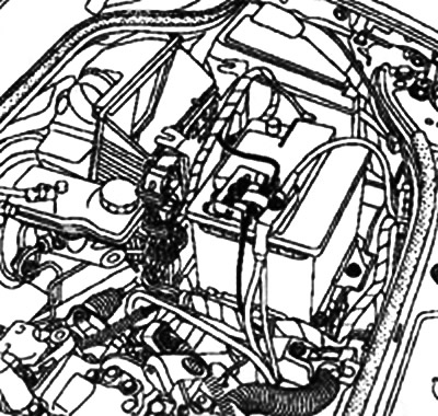
Remove the battery cover.
Disconnect the wires from the battery terminals, starting with the negative terminal.
Remove the engine oil pan guard.
Drain the oil from the gearbox.
Remove:
- front wheels;
- engine Top Covers;
- battery;
- shelf for battery;
- Injection system ECU with bracket;
- mass air flow sensor;
- air intake pipe.
Remove the wire harness holders.
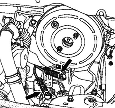
Disconnect the gear selector and shift cables from the transmission.
Disconnect both cables from the levers on the gearbox.
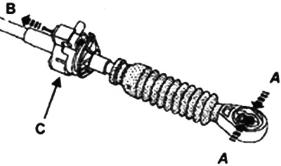
Squeeze the end of the cable at points (A), pull the lock in direction (B) and lift the cable at point (C).
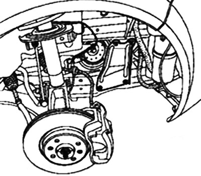
Unscrew the hub nut using the tool (Rou. 604-01).
Remove the ball joint of the tie rod end using the tool (Tav. 476) and the ball joint of the anti-roll bar.
Remove the suspension arm ball joint.
Disconnect the drive shaft from the steering knuckle.
Remove the drive shaft.
Secure the engine cooling system radiator assembly with the condenser to the upper cross member using twine.
Remove the side reinforcements.
Remove the radiator cross member.
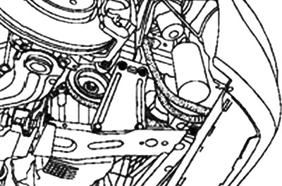
Remove the catalytic converter bracket from the clutch housing.
Unscrew the mounting bolts and remove the starter.
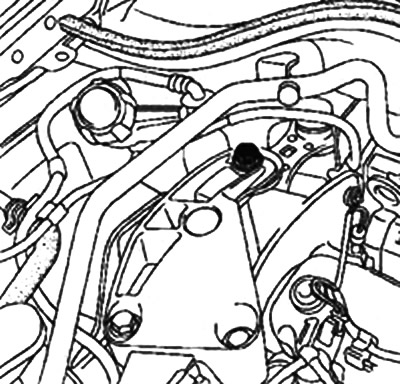
Remove the upper reaction rod.
Remove the lower reaction rod.
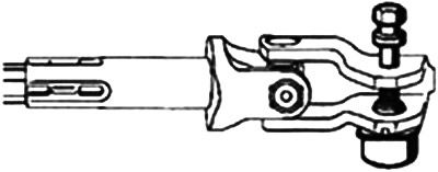
Remove the steering shaft universal joint fork.
Remove the subframe corner bracket.
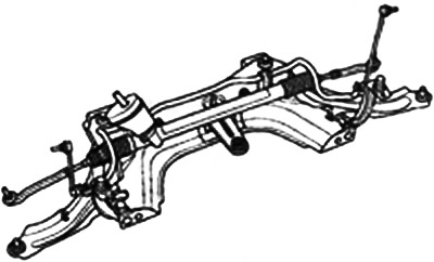
Remove the front suspension subframe.
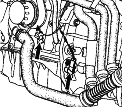
Disconnect the wiring harness from the reverse light switch and the wiring harness from the TDC sensor.
Using a syringe, remove the brake fluid from the reservoir to the nipple of the clutch master cylinder line.
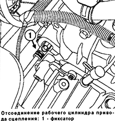
Disconnect the clutch slave cylinder by removing the retainer.
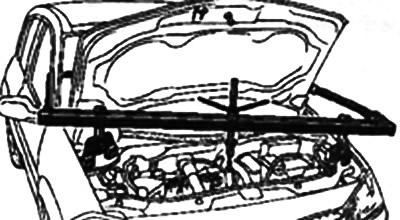
Install the engine support crossbar (Mot. 1453).
Remove the silent block of the gearbox support and the pendulum support of the gearbox.
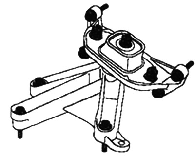
Remove the upper gearbox mounting bolts from the engine block.
Place a hydraulic jack under the gearbox.
Remove the lower bolts securing the gearbox to the engine block.
Remove the gearbox mounting studs.
Remove the gearbox.
Installation
Caution! Do not apply grease to the gearbox input shaft to avoid damaging the clutch slave cylinder and the gearbox input shaft splines.
Note: To prevent fluid leaks, be sure to replace the clutch slave cylinder when replacing the clutch housing.
Note: Make sure that the mounting bushings are present and correctly positioned to ensure the engine and gearbox are aligned with each other.
Installation is carried out in the reverse order of removal.
When installing, be sure to tighten the steering shaft cardan joint fork terminal bolt.
Tighten to the specified torque:
- wheel bolts (110 Nm);
- hub nut (280 Nm);
- nut for fastening the ball joint pin of the suspension arm (62 Nm);
- nut for fastening the ball joint pin of the steering rod end (37 Nm);
- anti-roll bar ball joint pin mounting nut (44 Nm);
- side panel mounting bolts (2 Nm);
- gearbox and starter mounting bolts to the engine (44 Nm);
- bolts for fastening the jet thrust to the engine (180 Nm);
- bolts for fastening the reaction rod to the subframe (105 Nm);
- pendulum support mounting bolts of the box (62 Nm);
- pendulum support mounting nut to the cushion (180 Nm);
- bolts of the terminal connection of the fork and the universal joint of the steering shaft (21 Nm);
- front radiator crossmember mounting bolts (105 Nm);
- rear radiator crossmember mounting bolts (210 Nm);
- subframe crossmember mounting bolts (62 Nm);
- rear subframe mounting bolts (140 Nm);
- bolts for fastening the connecting rods to the subframe (105 Nm);
- gearbox drain plug (25 Nm);
- gearbox filler plug (3 Nm).
Fill the gearbox with oil.
Caution: Be sure to bleed the clutch hydraulic system as follows:
- add brake fluid to the reservoir;
- bleed the clutch hydraulic drive;
- top up the brake fluid to the normal level.
Connect the wires to the battery terminals, starting with the positive terminal.