



Contents: Inspection 🠛 Assembly 🠛
Inspection
1. Before starting the inspection, it is necessary to clean the piston/connecting rod assemblies and remove the piston rings from them.
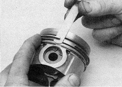
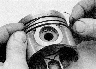
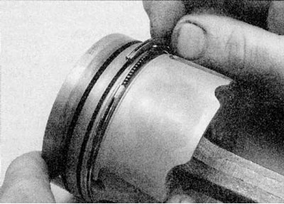
2. Carefully pry the rings apart and remove them from the piston crown. Use two or three old feeler gauges to prevent the rings from jumping into the now empty grooves (refer to the accompanying illustration). Please note that the oil scraper ring consists of two parts.
3. Clean off the main carbon deposits from the piston bottom. Then clean it with a wire brush or fine sandpaper.
4. Remove carbon deposits from the piston ring grooves using a piece of an old ring (break the old ring in half, working carefully so as not to cut your fingers). Be careful not to remove any metal along with the carbon deposits or scratch the walls of the grooves.
5. After removing the carbon deposits, clean the piston/connecting rod assembly with kerosene or a suitable solvent and dry it thoroughly. Make sure that the oil return holes in the ring grooves are not clogged.
6. If the pistons and cylinder walls are not damaged or worn out and if the cylinder block does not require regrinding, the old pistons can be installed. Normal piston wear is manifested by uniform vertical wear of its axial pressure surfaces and a small play of the upper ring in the groove. When assembling the engine, the piston rings must be replaced.
7. Carefully inspect each piston for cracks in the skirt, around the piston pin holes and between the ring grooves.
8. Inspect the piston skirt for damage and the piston crown for pinholes or burns. If the skirt is scratched or nicked, or the piston crown is gouged or burned, the engine may have overheated and/or misfired (the fuel mixture ratio or injection/ignition timing were incorrectly adjusted). Check the cooling and lubrication systems carefully. Burnt spots on the piston sides indicate that a gas leak has occurred. If any of the above damage is detected, identify the causes and eliminate them, otherwise the damage will occur again. On gasoline engines, the cause may be an air inlet leak, incorrect fuel/air mixture adjustment, or incorrect ignition timing. On diesel engines, incorrect fuel pump injection timing or a defective injector.
9. Piston corrosion indicates that coolant has leaked into the combustion chamber and/or crankcase. Find the cause of the leak and fix it.
10. If new rings are being installed on old pistons, measure the gap between the ring and the groove wall by inserting the new ring into the groove and measuring the gap with a feeler gauge. Check the gap in three or four places around each groove. No specific data is given by the manufacturer, but if the measured gap is greater than 0.10 mm, new pistons will be required. If the new ring fits too tightly into the groove, it is most likely due to dirt remaining in the groove.
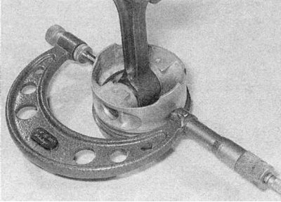
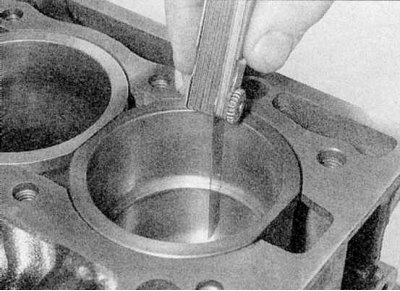
11a. Check the clearance between the pistons and the cylinder/liner walls by measuring the inner diameter of the liner or cylinder (refer to Section Removal and installation the intermediate shaft) and the piston diameter. Measure the piston diameter on the skirt perpendicular to the piston pin (refer to the illustrations). Subtract the piston diameter from the cylinder/liner diameter to get the clearance. If it is greater than the data given in the Specifications, the cylinder block must be bored and new pistons and rings installed. On E7J engines, new pistons and liners are supplied in matched pairs.
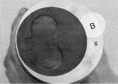
11b. The diameter mark is located on the piston bottom.
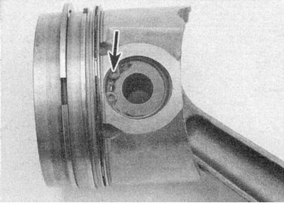
12a. Check the piston pin fit by rotating the piston and connecting rod in opposite directions. If there is play, this indicates excessive wear and the pistons and connecting rods should be separated (k7M and E7J engines). This should be entrusted to a Renault service station or an engine overhaul specialist.
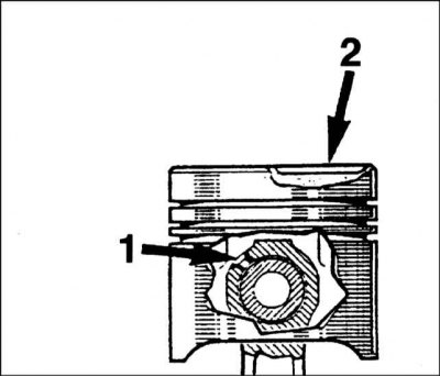
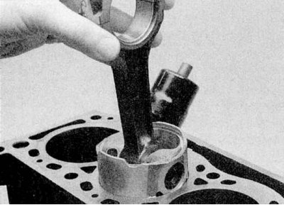
12b. Note that on diesel engines and F3R and F7R petrol engines the piston pins are secured with blocking rings. Note the position of the piston relative to the connecting rod (refer to the illustrations).
13a. Before installing the ring on the piston, check the clearances of the cuts (refer to the illustrations).
13b. No data is specified by the manufacturer, but the following values can be used as a guide: 0.50 mm for compression rings and slightly more for oil scraper rings. The gap cannot be adjusted in Renault rings.
Assembly
1a. Install new rings on the pistons (refer to the illustrations).
1b. Note that the second compression ring is tapered. Both compression rings should be installed with the word "TOP" facing up.
(Original version on our portal: «www.RenaultBook.ru»)
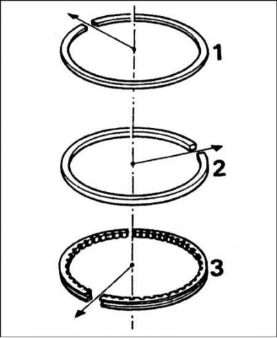
1c. Space the ring cut gaps evenly at 120° apart.
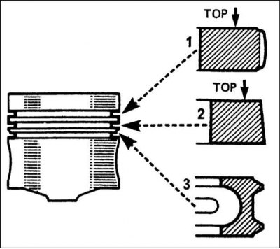
1 - Upper compression ring;
2 - Lower compression ring;
3 - Oil scraper ring.
2. Please note that on E7J engines, if new piston and liner assemblies are received, each piston is matched to its corresponding liner and they must not be mixed up.