
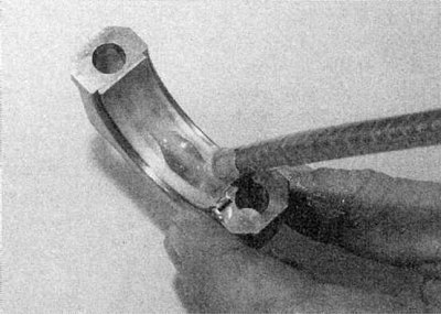
2. Insert the liners into place in the connecting rods and caps. Make sure the mounting tabs fit into the slots in the cranks.
E7J petrol engine
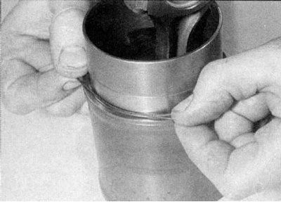
1. Lay out the four sleeves in order of installation, working surface down. Install o-rings at the base of each sleeve (refer to accompanying illustration).
2. Lubricate the pistons and piston rings, then lay each piston/connecting rod assembly with the appropriate sleeve
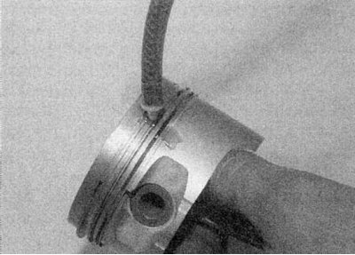
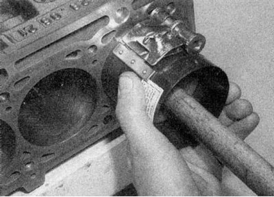
3. Start assembly with piston No. 1, after checking that the cuts of the piston rings are evenly spaced from each other (at 120°). Compress the piston rings with a special tool.
4. Insert the piston/rod assembly into the liner base. Make sure the arrow on the piston crown points towards the flywheel/drive plate. Using a block or hammer handle, hammer the piston into the sleeve until the piston crown is approximately 25 mm from the top of the sleeve.
5. Repeat the procedure for the remaining three piston and sleeve assemblies.
6. Turn the crankshaft so that the connecting rod neck No. 1 is located at the bottom dead center.
7. With the liner O-ring in place, place the liner with the piston/rod assembly in the cylinder block. The arrow on the piston crown must point towards the flywheel/drive plate.
8. To measure the operating clearance of the connecting rod bearing, see the information in Section Inspection of the crankshaft.
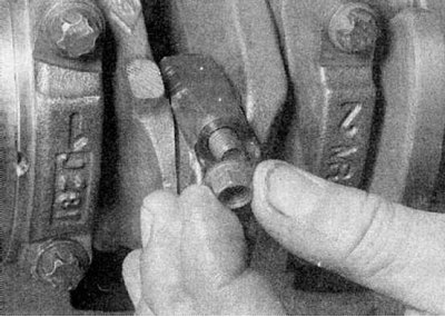
9. With the sleeve/piston assembly in place, secure the sleeve with a bolt and washer or clamp (refer to accompanying illustration).
10. Repeat the above procedures for the remaining assemblies.
All other engines
1. Lubricate #1 piston and piston rings and make sure piston ring cuts are 120°apart (refer to accompanying illustration).
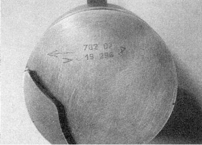
2. Install the compressor on the #1 piston, then insert the piston and connecting rod into the #1 cylinder. On petrol engines, arrow "V" should point towards the flywheel. On F8Q engines, the notch in the piston crown must be on the side of the engine's oil filter.
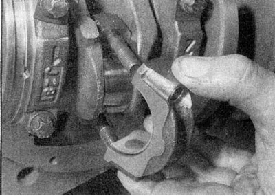
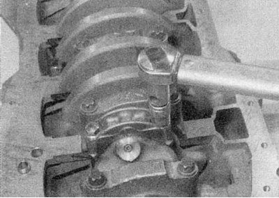
3. With the crankshaft journal at bottom dead center, carefully insert the piston into the cylinder while guiding the connecting rod onto the crankshaft journal (refer to illustrations).
4. To measure the operating clearance of the connecting rod bearing, see the information in Section Inspection of the crankshaft.
5. Repeat the above procedures with the remaining piston/rod assemblies.
Final installation
1. After checking the working clearance of all connecting rod journals, wash off all traces of Plastigauge from the liners and crankpins of the crankshaft.
2a. Lubricate the connecting rod bearings liberally.
2b. Lubricate the crankshaft journals liberally.
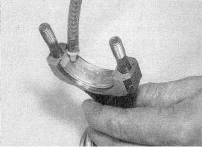
2c. Install bearing caps.
2d. Screw nuts.
2e. Tighten the nuts/bolts of the covers to the torque given in the Specifications. Each time checking that the crankshaft rotates freely.
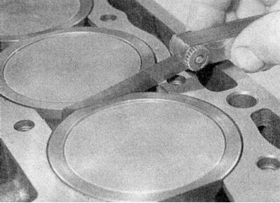
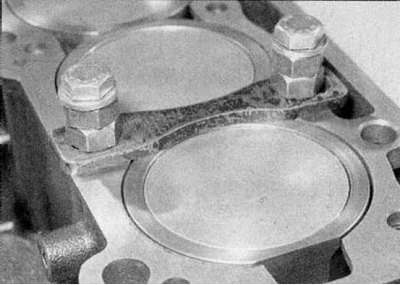
2f. On the E7J engine, check that all liners are correctly positioned in relation to each other (a probe 0.1 mm thick should pass freely into the gaps between them). If this is not the case, one or more piston/liner assemblies may need to be swapped to achieve this clearance (refer to illustrations).
3. Finally, install the oil pump, sump and cylinder head.