
Turbocharged diesel engine
2. Lubricate the hole for the piston pin, assemble the piston with the connecting rod (see illustration), the location of the lubrication hole in the connecting rod bearing relative to the recess in the piston crown should be as shown in the figure.
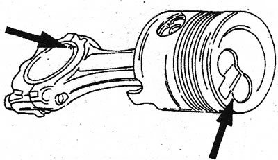
13.2 Landmarks when assembling pistons and connecting rods of a diesel engine
3. Push the piston pin into the hole with your finger, then put on the retaining rings on the left and right. Make sure the rings fit exactly into the grooves.
4. Put the piston rings on the pistons. The top ring is labeled «Thor». This side should be viewed from above. The piston ring lock value is preset and cannot be changed. Lubricate the piston rings well and install on the piston so that each subsequent lock is 120°apart from the previous one (see illustration).
V6 engine
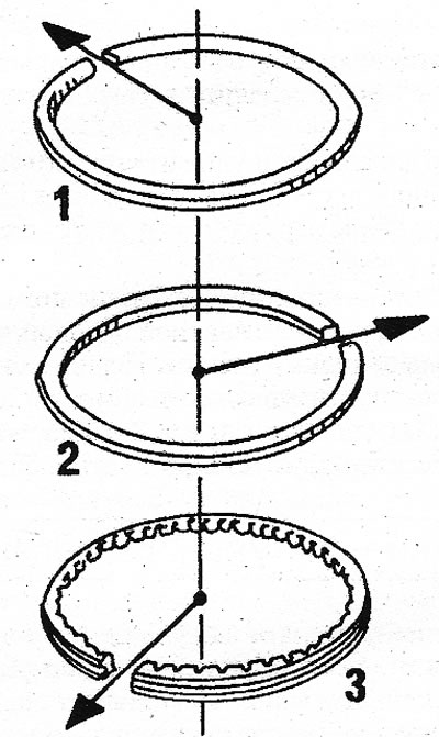
13.4 Piston ring locks must be positioned as shown
5. The assembly of the pistons and connecting rods of the V6 engine is carried out in the same way as described for the turbocharged diesel engine, since circlips are also used to install the piston pins. However, note the following differences:
6. There is a mark on the bottom of the piston «Vom» (usually «AU») (see illustration). Install the pistons and connecting rods of cylinders 1 to 3 in such a way that the raised side of the connecting rod is located opposite from the mark «wat» sides.
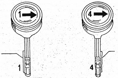
13.6 Guides for assembling pistons and connecting rods of the V6 engine. Pay attention to how the raised surfaces of the connecting rods are located in relation to the markings «Vorn»
1. Cylinders 1 to 3; 4. Cylinders 4 to 6
7. When assembling sets of cylinders 4 to 6, the connecting rod elevation must be on the same side as the mark «wat». The illustration shows piston/connecting rod assemblies for each cylinder bank. Cylinders 1 to 3 are located on the left when viewed from the flywheel side.
8. Assemble the pistons and connecting rods as described for the diesel engine. To warm the pistons, you can put them in hot water. Make sure the circlips are inserted correctly. Evenly place the ring cuts around the piston (see illustration 13.4). Tag rings «Thor» or «Haut» set so that the marks are read from above.
9. After assembly, check all six sets again.
Petrol 4-cylinder engines
10. Place the connecting rods on the hot plate. In this case, only their heads should lie on the tile (see illustration). For connecting rods with fusible fingers, constantly monitor the temperature, it should not exceed 250°C. Install the connecting rod cap so that there is a gap of 1.0 mm between the bearing surface and the connecting rod cap.
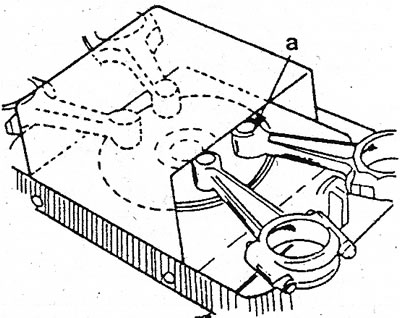
13.10 Heating the connecting rods. Only heads can be placed on a tile «A»
11. Assemble pistons and connecting rods for installation. The arrows on the piston crown should point towards the flywheel. The oil injection hole in the connecting rod must be on the same side as the oil filter. For connecting rods without an oil hole, the recess for the connecting rod bearing shell must be on the oil filter side.
12. Install the bushing on the lug, position the piston over the mounting bushing and secure as shown (see illustration).
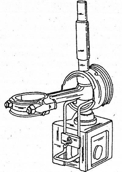
13.12 Pressing in the piston pin
13. Place the piston pin on the punch, and on the other hand, screw on the conical guide washer without tightening it. Lubricate the finger and punch well.
14. Quickly remove the connecting rod from the electric stove and insert into the piston.
15. Insert your finger. If necessary, move the connecting rod back and forth to avoid distortion. Push the piston pin in as far as it will go. A special tool will ensure accurate pin pressing. After a few seconds, remove the piston from its support and check that the piston moves freely on the pin after the pin has cooled. Installation must be done as quickly as possible so that the connecting rod head does not have time to cool. t < 1
16. Turn out an adjusting punch from the piston and establish other pistons in the way described above.
17. Using an oiler, spray engine oil at the pin location. Make sure the pistons can move easily.
18. In turn, install the rings in the piston grooves. Both upper rings must be set with a mark «Thor» up. Double check each ring before installing as it is easy to make mistakes. Use the special tool to install the piston rings. You can also use three thin metal plates. Rings can break easily, so install them with great care.
19. Lubricate the piston rings well and put them on the piston from the outside, evenly placing the locks of the rings along the perimeter of the piston. The locks must be 120°apart from each other, (see illustration 13.4).