
- A) Before assembling, check that all parts are clean and free from foreign bodies.
- b) Apply a thin coat of oil to all parts that rotate or slide. This must be done before assembly, and not after the parts have already been assembled. It is especially important to generously lubricate the pistons, piston rings and cylinder walls with engine oil.
- With) If the engine has been completely disassembled, thoroughly clean all parts of the cylinder block. When partially disassembling, make sure that foreign bodies do not get into unassembled parts of the engine, or into cavities. All openings and cavities must either be plugged with rags or covered with a cloth.
- d) Lubrication channels and holes are best cleaned with compressed air. If you do not have such an opportunity, the channels and holes can be cleaned with a wooden stick, in no case with metal objects. O-rings, gaskets, etc. should always be replaced with new ones. Never reuse them.
- e) The specifications indicate the wear limits of the most moving parts. In case you are in doubt, or the wear limit will soon be reached, it is better to replace the part.
2. The following description is given separately for each engine group.
Engines with a volume of 1995/2165 cm33 (J6R/ J7R/J7T)
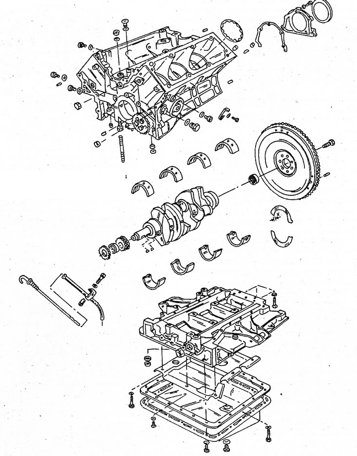
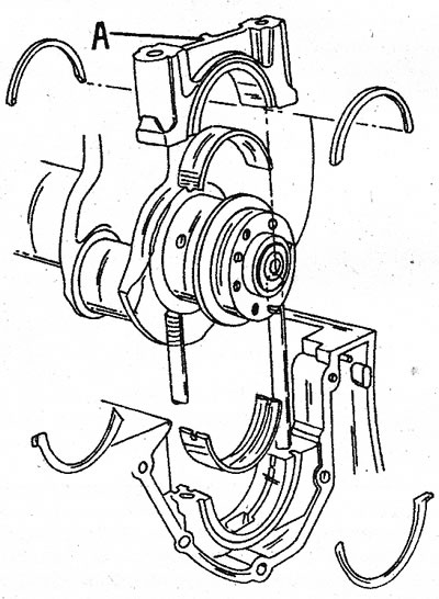
3. Thoroughly clean the cylinder block. Remove the channel plugs and blow out the channels. Three plugs are installed on the side wall of the cylinder block and one on the end. Unscrew the plugs with a hex wrench. The tightening torque of the side plugs is 40 Nm, the end cap is 80 Nm. When assembling, be guided by the illustration, which shows the position of individual parts.
3.3 Engine type internals «J». Similar parts also in turbocharged petrol and diesel engines
4. If possible, install the cylinder block on an assembly stand or on a workbench (open side up). Place the main bearing shells on the journals. In doing so, pay attention to the following:
- A) Bearing shells No. 1, 3 and 5 are the same and have two lubrication holes. If these inserts are installed again, they must return to their original position.
- b) Bearing shells #2 and #4 are the same and have three lubrication holes and a groove. In case of reassembly, they must be installed in their original position.
5. Lubricate the bearing shells, as well as the main bearing journals and the connecting rod journals of the crankshaft with engine oil. Carefully insert the crankshaft into the crankcase and turn several times so that the bearings can properly fit into place.
6. Insert thrust washers for axial clearance with an anti-friction alloy surface onto the crankshaft. Insert the lower shells into the bearing caps.
7. Establish covers of radical bearings according to their marking and well lock up. Pay attention to the following points:
- A) Install the bushings and caps on the bearings No. 2, 3 and 4 and screw in the bolts without tightening them. Make sure all dowel pins are securely fastened.
- b) Bearing caps #1 and #5 can be mounted using two different methods, i.e. either silicone grease is applied to the cover or a safety seal is used between the cover and the cylinder block. Under normal conditions, you can limit yourself to the second method (sealant), however you need to have a sealant (CAF 4/60 THIXO), which can be purchased from your dealer.
- With) No. 1 and No. 5 main bearing caps temporarily assembled without bead O-rings, assemble them completely. Tighten the bearing caps to the specified torque.
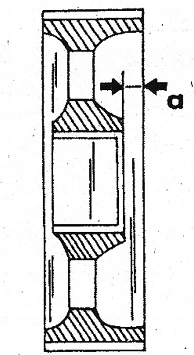
- d) Measure bearing cap clearance (using a caliper) left and right as shown in illustration 3.7a. If the gap is less than 5.0 mm, the thickness of the seal should be 5.10 mm; if the gap is greater than 5.0mm, the thickness of the seal should be 5.40mm. The seal has a white marking and can therefore be recognized.
- e) Lubricate the edges of both bearing caps with sealant. The sealing washer has holes that must not be clogged with sealant, since through them the oil enters the crankcase.
- f) Insert the bushings into the bearing caps. Lubricate the inserts and covers well before this.
- g) Screw two M12x1.50 studs into the cylinder block (in place of the bearing cover bolts) and put the bearing cover on them. To protect the sealing plates, place pieces of aluminum foil on each side between the cover and the sealing plate. Illustration 3.7b shows how one of the covers is installed.
- h) Remove the foil, unscrew both studs and screw the bolts into the main bearing cap. Tighten all bearing cap bolts to 88-98 Nm. Make a few control turns of the crankshaft to check its fastening.
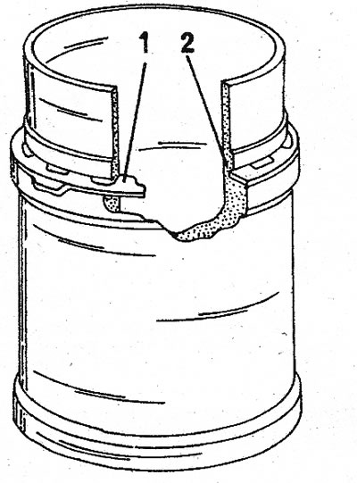
- i) Cut off the ends of both sealing plates with a sharp knife (see illustration 3.7c), so that the edges of the material protrude by 0.5 - 0.7 mm. As a result, additional sealing of the oil pan is ensured.
3.7a The value indicated between the arrows is measured on each side. The bottom picture shows the position of the seal (1) in relation to the surface «A»
3.7b Fitting the rear bearing cover. Arrows show both pins. Both aluminum plates are visible to the left and right. The front bearing cap is mounted in the same way
3.7c After installing the bearing cover, cut off the protruding material from the
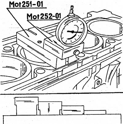
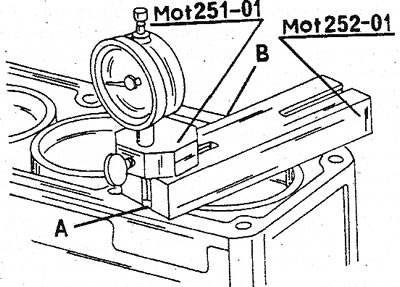
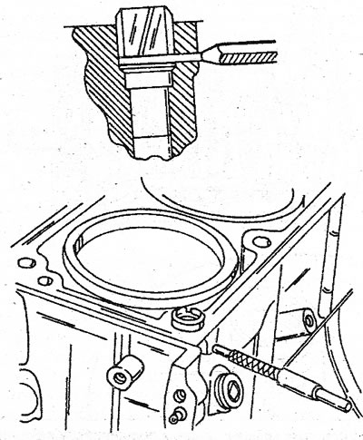
8. Measure the axial clearance of the crankshaft. For this, a micrometer with a dial is best suited, which is installed in the cylinder block (see illustration). Install a feeler gauge on the end of the crankshaft (flywheel side). Now move the crankshaft back and forth with a square rod inserted between one of the crankshaft cheeks and the crankcase. The value that the micrometer shows in this case is the axial clearance, which must correspond to the data in the specifications. If necessary, replace the shims in the middle main bearing.
3.8 Measuring the axial clearance of the crankshaft using a micrometer with a dial. The measuring probe is installed on the end of the crankshaft
9. Establish epiploons in forward and back parts of the block of cylinders. Usually a punch is used for installation. Apply grease to the outside of the seal. If the same crankshaft is installed, which happens most often, and the working surface of the crankshaft is worn out at the point of friction of the old oil seal, then the new oil seal must be driven 1.5 mm deeper.
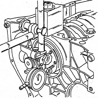
10. To mount the front oil seal, use a piece of tubing of the appropriate diameter and a large disc. Lubricate the oil seal from the outside and insert it into the hole. Install a piece of tube with a disc and screw a long bolt into the crankshaft (see illustration). Cut off the edges of the O-ring that protrude beyond the outer surface. If necessary, hammer the gland 1.5 mm deep.
3.10 Installing the crankshaft front O-ring. Shown «piece of tube» is a special tool
11. Before installing the flywheel, stock up on a small amount of sealant «Loctite Autoform» (or other sealant). Lubricate a well-cleaned surface of the flywheel with this product and install the flywheel. If a lock washer has been installed, the same must be used (always change to a new one). Flywheel bolts should also always be changed. Lubricate the threads with thread lubricant and tighten the bolts evenly to 60 Nm. After installation, check the surface of the flywheel for runout. To do this, position the dial micrometer as shown in illustration 3.8. Place a feeler gauge on the rotating surface of the flywheel.
12. If a lock washer is used, bend the tab located on its surface with pliers and press.
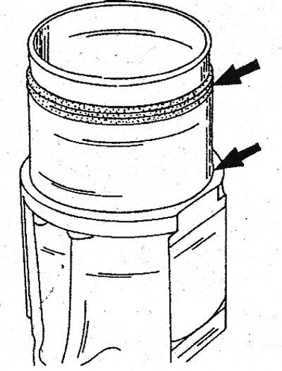
13. Put on sealing rings on the basis of sleeves of cylinders. They serve only as a seal for the coolant. The cylinder liners are located directly in the engine block. Measure protrusion of sleeves from the block of cylinders. To do this, push the sleeves into the cylinders by hand until they stop. If old sleeves are used, they must be installed in accordance with their numbers. Sealing. Don't wear rings at this time.
14. Measure the liner protrusion as follows:
15. Install a micrometer on the top of the surface of the cylinder block (see illustration). Always start with the first cylinder.
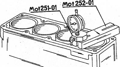
3.15 Special tools for measuring cylinder liner protrusion
16. Turn the micrometer holder so that the control probe of the micrometer is on the upper edge of the cylinder liner. Set the micrometer needle to zero in this position.
17. Turn the micrometer holder now so that the control probe hits the surface of the cylinder block. The micrometer readings are the size of the sleeve gap and are 0.08 - 0.15 mm.
18. If you don't have a dial micrometer, place a metal ruler on the cylinder liner and measure the gap between the liner and the surface of the cylinder block with a feeler gauge.
19. In the same way, the protrusion of the remaining sleeves is measured. Liners mark with cylinder number (in case new sleeves are installed) and measure the difference between the two sleeves side by side. It should not exceed 0.04 mm. If the difference is greater, try swapping the liners in the cylinders (as long as they are all new) and repeat measurements.
20. Finally, remove the liners from the cylinders.
21. Further assembly of the engine is carried out in the following sequence:
22. Lubricate the pistons and cylinder liners with oil. Do not use a brush for this.
23. Insert the pistons and connecting rods into the holes on the back side of the cylinder liners. Use a special tool designed to push the piston rings into the piston grooves. The mounting ring must match the diameter. The rings are fragile, so work must be done with great care.
24. The piston should protrude from the cylinder at the level of the piston pin. Slide new O-rings onto the bottom of the liners and insert the liners with pistons and connecting rods into the cylinder block. In doing so, pay attention to the following points:
25. If the same kits are installed, kit No. 1 is installed on the rear of the engine. Arrows on the bottoms: pistons should point to the flywheel. If pistons are installed, all arrows should point as shown (see illustration).
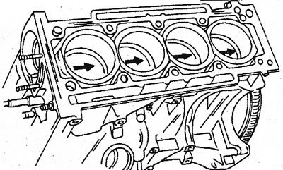
3.25 Marking of pistons. The arrows must point as shown
26. The numbers on the connecting rod bearings and bearing caps must be on the same side.
27. Installed cylinder liners again block in the cylinder block using a special tool. Be aware that pistons and connecting rods can also fall out if you inadvertently turn the engine.
28. Insert the bearing into the connecting rod and lubricate the bearing surfaces with oil. The connecting rod and bearing are provided with lubrication holes that must be covered.
29. Carefully move the connecting rod to the crankshaft journal. The two connecting rod journals must be at BDC to facilitate installation.
30. Place the insert in the appropriate connecting rod cap and install the cap on the connecting rod in accordance with. mark.
31. Tighten the connecting rod bearing nut to the specified torque. The different tightening torques for the individual motors must be observed.
32. Install the other two sets in the same way.
33. Together with the flywheel, turn the crankshaft to check the crank mechanism for binding. Then make sure not to pinch your fingers between the gear rim of the flywheel crown and the crankshaft housing.
34. Push the oil pump onto the dowel pins and tighten the bolts.
35. Lubricate the intermediate shaft journals, slide the shaft into the cylinder block and insert the key into the shaft groove. Align the bolt hole in the lug, insert the bolt and tighten (see illustration 3.35a). Fill the space around the intermediate shaft at the other end with engine oil to give the shaft an initial lubrication and put on the cover with a new paper gasket and a new oil seal. When installing, do not damage the oil seal and ensure that it is correctly centered. Illustration 3.35b shows where the cover is located.
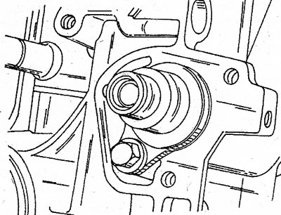
3.35a Mounting the intermediate shaft at the end of the cylinder block
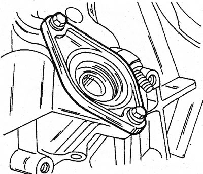
3.35b Intermediate shaft cover at the rear of the cylinder block
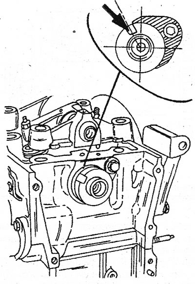
36. Hammer the key into the intermediate shaft and put on the pulley. As you will notice, the pulley is not symmetrical (see illustration). Deeper side «A» must be turned towards the shaft, i.e. to the cylinder block. Rotate the shaft several times to check its movement.
3.36 Installing the intermediate shaft pulley. Side with wider wall «A» must be turned towards the shaft
37. The following parts are mounted in the specified sequence:
38. Install the oil pan with a new seal.
39. Install the water pump.
40. Install the water pump outlet tube and pulley.
41. Install the cylinder head. The two guide bolts should be made from old cylinder head bolts. To do this, saw off the heads of the bolts and saw through the grooves for the screwdriver. Screw the guide bolts into the two diagonal corners of the cylinder head.
42. Put sealant on both guide bolts and both mounting sleeves in the cylinder head.
43. Install the cylinder head, first on both bolts and then on both mounting sleeves. Tap the head well with a plastic mallet. When mounting the head, connect the cooling jacket outlet.
44. Remove both guide bolts.
45. Track, that tension bolts of yokes have been weakened and put on yokes on a head. Make sure that the thrust washer in rocker arm support #5 falls into the groove of the camshaft. The rounded ends of the rocker arms must fit into the bowls of the push rods.
46. Lubricate the mounting bolts and washers of the cylinder head with engine oil and insert into the holes. Then tighten them in the specified sequence (see illustration 2.6a) tightening force 50 Nm. Then with another tightening torque of 80 Nm, loosen by a quarter of a turn and immediately re-tighten with a tightening torque of 88-98 Nm.
47. Adjust valve clearances as described below.
48. Install the ignition distributor and turn the camshaft until the larger segment of the drive gear is at the top.
49. Tighten the clamps of the connecting hose in the cylinder head.
50. Fit the toothed drive belt tensioners and tension the belt as described in a separate chapter.
51. Install the cylinder head cover, intake and exhaust manifolds, carburetor, fuel line, etc. in the reverse order of disassembly.
52. Press the friction disc against the flywheel so that the longer side of the sleeve is on the outside, and install the clutch on the flywheel. Center the clutch. Tighten the bolts evenly in a circular pattern.
53. After the engine is installed, start it and, when it reaches operating temperature, turn it off again.
54. Let the engine cool down (at least 2 hours) and remove the cylinder head cover. Measure valve clearance and adjust if necessary. In this case, the bolts are tightened in the sequence shown in illustration 2.6a. Loosen each bolt half a turn and tighten again to 88-98 Nm.
Assembling a turbocharged diesel engine
55. Since the design of this engine is based on the engines just described, all the above instructions also apply to diesel engines. However, there are differences, for example when installing the cylinder head (when assembling the engine, follow the instructions until the flywheel is installed). The dimensions of the cylinder liners of a diesel engine are also different from those of a gasoline engine:
56. O-rings are located at the bottom of the sleeves. They serve only as a seal for the coolant. The liners are inserted directly into the cylinder block. Measure protrusion of sleeves from the block of cylinders. To do this, push the sleeve into the cylinder by hand until it stops. If non-new parts are used, they must be installed according to the numbers. Do not fasten the sealing rings at this time. Measure the liner protrusion as follows:
57. Install dial micrometer on top of cylinder block (see illustration). Always start with the first cylinder.
3.57 Determine the dimensions of the cylinder liner using special tools. The picture below shows how the sleeves are arranged
58. Move the micrometer holder so that the control probe stops at the top edge of the sleeve. Set the micrometer reading to zero in this position.
59. Then move the micrometer holder so that the control probe is on the surface of the cylinder block. The indication of the micrometer is the setting size and is 0.05-0.12 mm.
60. If you do not have a micrometer, put a steel ruler on the surface of the sleeve and use a feeler gauge to measure the gap between the sleeve and the surface of the cylinder block.
61. Take the same measurements alternately on other sleeves. Mark the cylinder number on the liner (in case new sleeves are installed) and set the difference between the gaps of two adjacent sleeves. It should be no more than 0.04 mm. If the difference is greater, swap the liners in the cylinders, making measurements all the time. It is also possible to insert the sleeves in such a way that the difference between the protrusion of the sleeves gradually decreases, i.e. either from the first cylinder to the fourth, or from the fourth to the first, as shown in the bottom figure of illustration 3.57.
62. Finally, remove the liners from the cylinders and mark them with the numbers of the respective cylinders.
63. Further assembly of the engine occurs in the following sequence:
64. Lubricate the pistons and cylinder liners with oil. Do not use a brush for this.
65. Push the pistons and connecting rods into the sleeves from the underside. Using the special tool, install the piston rings into the grooves. The ring must match the diameter of the piston. Rings are fragile, so work must be done very carefully.
66. Put new O-rings on the bottom of the sleeve (see illustration 3.66) and insert the liners complete with pistons and connecting rods into the cylinder block. In doing so, pay attention to the following points:
- A) If the old parts are installed, set No. 1 is installed from the side of the engine flywheel. Arrows on the bottom of the piston (drawn during disassembly on old or new pistons) should point to the flywheel. If the pistons are installed correctly, all arrows should point to the same side of the engine (see illustration 3.25).
- b) The combustion chambers in the piston crowns must point towards the intermediate shaft.
- With) The connecting rod bearing and cap numbers must be on the same side. The connecting rod oil hole must be on the opposite side of the intermediate shaft (in case the connecting rods are drilled).
3.66 O-rings are installed on the sleeves at the indicated points
67. Secure the sleeves installed in the cylinder block with bushings so that they cannot fall out again. Remember that pistons and connecting rods can also fall out if the engine is turned in a careless way.
68. Insert the bearing shells into the appropriate connecting rods (in the old connecting rods, if no replacement was made) and lubricate the bearing surfaces.
69. Carefully bring the connecting rods to the crankshaft journals. Two of the crankpins should be at BDC to facilitate assembly.
70. Insert the insert into the corresponding connecting rod cover and install the covers on the connecting rod in accordance with the markings.
71. Tighten the connecting rod bearing nuts to 65 Nm.
72. Install both other sets in the same way.
73. Rotate the crankshaft by turning the flywheel to check for even crankshaft travel.
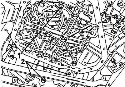
74. Place the oil pump on the dowel pins and tighten the bolts to 40-45 Nm. It is possible that the engine will be equipped with a plate on the lower surface of the crankcase (see illustration). To mount and install the oil pump, bolts of different sizes are used, see Fig. «Engine lubrication system». Bolt (1) holds the oil strainer, bolts (2) - fastening bolts.
3.74 Plate mounted on the lower surface of the crankcase. The plate can also be installed on gasoline engines
75. Lubricate the intermediate shaft journals, slide the shaft into the cylinder block and install the key in the shaft groove. Align the screw hole, insert the bolt and tighten (see illustration 3.35a). Fill the space around the intermediate shaft at the other end with engine oil to provide the shaft with initial lubrication and close the cover with a new paper gasket and a new oil seal. When installing the cover, the gland must not be damaged and at the same time be well centered. See illustration 3.35b for cover location.
76. Hammer the key into the intermediate shaft and put on the pulley. On gasoline engines, mounting is done in the same way. Note that the pulley is not symmetrical (see illustration 3.35c). Wider side «A» must be turned towards the shaft, i.e. to the cylinder block. Block the intermediate shaft and tighten the bolt. Rotate the shaft several times to check its movement.
77. Install vacuum pump with drive mechanism (see illustration). Lubricate the pump shaft liberally with engine oil after installation so that the pump receives lubrication when the engine is first started. Push the pump all the way in. When the bearing surfaces touch, tighten the bolts. Rotate the intermediate shaft with the vacuum pump and oil pump assembly several times to check their connection.
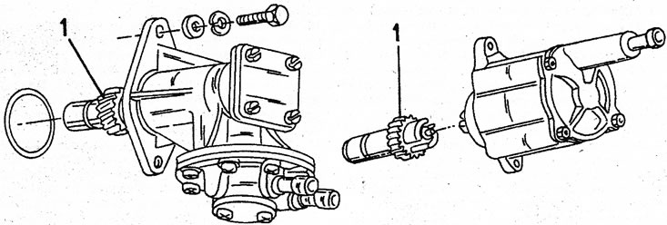
3.77 View of both vacuum pumps. pinion gear (1) or attached to the pump (APG), or connected to the pump together with the shaft (Barmac)
78. Install the following parts in the sequence shown:
- Install the oil pan with a new seal. Cm. «Engine lubrication system».
- Install the water pump. Cm. «Cooling system».
- Install the water pump outlet pipe and pulley.
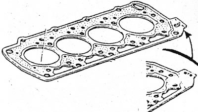
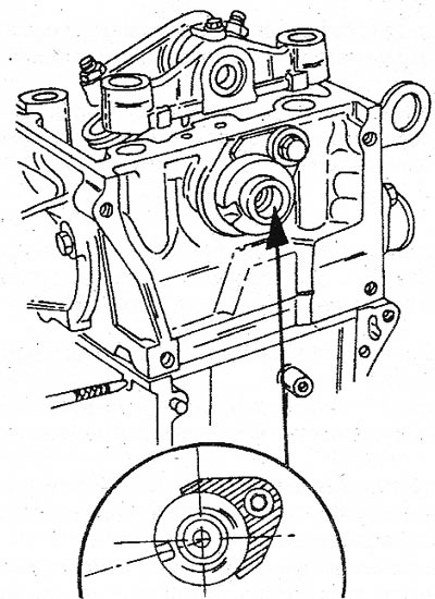
- Install the cylinder head. Before installing, be sure to determine the thickness of the cylinder head gasket. Cylinder head gaskets come in 1.6, 1.7 and 1.8 mm. Choose the right one. A micrometer can be used for this purpose. Otherwise, use a ruler.
79. Three main factors necessary for the perfect operation of the engine:
- The pistons must protrude according to the prescribed value above the surface of the cylinder head. This protrusion will be balanced when the cylinder head gasket is installed.
- The valves must lie deep enough in their seats. If the valves burn out, remove the top layer.
- The valve heads must fit exactly on the piston crowns. Carrying out control is quite difficult and requires special tools. If the installation dimensions of the pistons and valves have been correctly determined, there is no need for such control.
80. Do the following work:
81. If the prescribed locking pins have been used, tighten the fastening bolts with a tightening torque of 50 Nm.
82. Turn the crankshaft so that the piston of the first cylinder is located near the TDC. If you have special tools (see illustration), install a dial micrometer or multimeter on the cylinder block wall. If a ruler and measuring probe are used, they are also mounted on the wall. Accurately set TDC and measure how far each piston protrudes from the surface of the cylinder block. Avoid pressing on the probe or piston while taking measurements. Write down the resulting value.
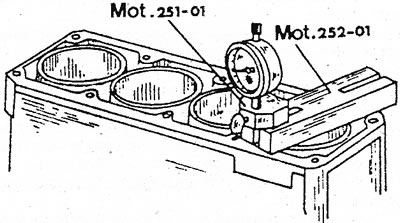
3.82 Measure the value of the output of the pistons from the surface of the cylinder block
83. Measure the piston output on the opposite side of the cylinder block in the same way and also record the result.
84. Now find the average of the results obtained, i.e. sum both values and divide by «2».
85. Thus find the values for all pistons. Turn the crankshaft accordingly to the TDC of the measured piston. The piston with the largest output determines the thickness of the cylinder head gasket. The resulting value should be considered as follows:
- In case the average output value is less than 0.96mm, install a 1.6mm thick spacer. This gasket can often be recognized externally by two holes (see illustration).
- If the average output is 0.96-1.04mm, install a 1.7mm thick spacer.
- In case the average output value is greater than 1.04mm, install a 1.8mm thick spacer.
3.85 The cylinder head gaskets are marked in the indicated location, in this case with two holes (1.6mm)
86. To install the cylinder head, use two guide bolts from the old cylinder head bolts. To do this, saw off the head of the bolt and cut the remaining bolt into a length of 150 mm. Make a hole for the screwdriver. Screw the guide bolts into the two diagonal corners of the cylinder head.
87. Place the cylinder head gasket on both guide bolts and both dowel sleeves.
88. Establish a head of the block of cylinders, at first on both pins and then on both adjusting plugs. Tap the head well with a plastic mallet.
89. Remove both guide bolts.
90. Lubricate the cylinder head bolts and washers with engine oil and insert into the holes. Before installing the cylinder head, loosen the rear mounting of the fuel pump.
91. Tighten all cylinder head bolts in correct sequence (see illustration 2.25) tightening force 30 Nm.
92. In the same sequence, tighten the bolts with a tightening force of 50 Nm, then again with a force of 95-105 Nm.
93. Wait a while and tighten the bolts again to 105 Nm.
94. After the engine has been running for 20 minutes and has cooled down for at least 2 hours and 30 minutes, tighten the cylinder head fasteners as follows:
95. Loosen the rear mounting of the fuel pump.
96. Loosen bolt #1 half a turn and tighten again to 95 - 105 Nm.
97. Do the same with the other bolts, following the tightening sequence.
98. Without loosening the bolts, tighten them again with a tightening torque of 95-105 Nm. Finally, reattach the fuel pump.
99. Install the rocker arms and adjust the valve clearance as described in the relevant chapter for the diesel engine.
100. Install the timing belt tensioner and guides (see relevant chapter).
101. Install the cylinder head cover, intake and exhaust manifolds and all other removed components in reverse order.
V6 engine assembly
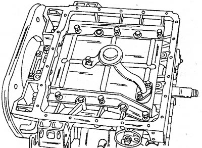
102. Illustration 3.102 shows the location of the assembly parts of the cylinder block, crankshaft, etc. If a new crankshaft is installed and the car has a manual transmission, it is necessary to rearrange the crankshaft primary bearing. New crankshafts do not have primary bearings. Before installing the bearing, lubricate its outer surface with special grease.
3.102 The location of the assembly components of the cylinder block (V6 engine)
103.Before assembling, check the installation dimensions of the cylinder liners in each row. The sleeve should protrude from the surface of the cylinder block by 0.13-0.20 mm if the lower sealing ring is installed. Do not allow the protrusion to grow. Although there is a special measuring device, nevertheless, measurements can be carried out using a measuring probe. Measurements are made as follows:
104. Set the micrometer (see illustration) on top of the cylinder block and measure the level difference between the cylinder block surface and the liner surface.
3.104 Special tool for measuring the installation dimension of the cylinder liner (V6 engine)
105. From both results, choose the larger value and subtract 0.20 from it to get the theoretical O-ring thickness at the bottom surface.
106. Install an o-ring of the calculated thickness or slightly less. O-rings are divided into three sizes and are marked with three colors for recognition. The following O-rings are available for you:
- Red 0.116 mm
- Colorless 0.136 mm
- Blue 0.166 mm
107. Put an O-ring of suitable thickness on the cylinder liner. O-rings have teeth on the inner surface that must be pushed into the recess of the cylinder liner (see illustration).
3.107 When installing O-rings on sleeves, teeth (1) inserted into slots (2)
108. Push the sleeves in such a way that the color of the ring is visible.
109. Check the installation size again, as shown in illustration 3.104. If necessary, namely:
- A) If the difference between the sizes of two adjacent sleeves is not more than 0.04 mm.
- b) If the surfaces of the sleeves of one row lie on the same level
110. Change the O-ring thickness. If any differences are established, the sleeves must be positioned as shown in illustration 3.57 (for diesel engine).
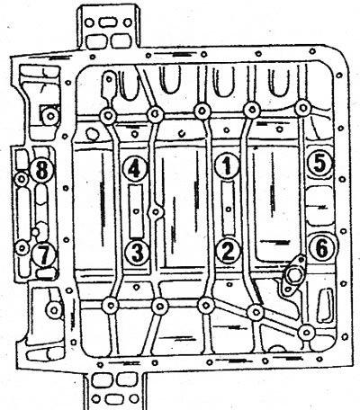
112. Once all O-rings have been selected, mark the liners with the appropriate cylinder numbers. The countdown starts from the flywheel. The liners of the left cylinder head are marked 1,2 and 3. The liners of the opposite cylinder head are 4, 5 and 6, respectively.
113. Remove the sleeves one by one and set them aside with the o-rings. Otherwise, if they get mixed up, you will have to take measurements again.
114. Turn the cylinder block upside down and clean the cylinders of foreign particles.
115. Lay the top loose leaf of the bearing in a case of a crankshaft. The guide lugs must fit into the corresponding grooves in the bearing caps. Liners with oil grooves are installed in the crankshaft crankcase; bushing without oil grooves in the integrated bearing cap. Lubricate installed bearings well (if possible, do not use a brush).
116. Carefully slide the crankshaft into the bearing. Position the top shims with the oil hole toward the crankshaft. The shims on the underside have a tab at the end that fits into the corresponding recess. In addition, the washers have a copper surface and an oil channel. The illustration shows the end of the crankshaft with liners and shims.
3.116 View of the end of the crankshaft. Bearing cap protrusion (A) must face the pulley
117. Install the front and rear bearing caps with liners in the crankcase (the guides must fit into the recesses). ledge «A» in the bearing cap (see illustration 3.116) must face the pulley. Using a special tool, secure the bearing caps (see illustration 2.63). Tighten the bearing cap nuts to 30 Nm and then loosen again.
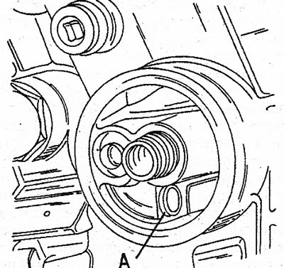
118. Measure the axial clearance of the crankshaft. To do this, install a micrometer with a dial on the cylinder block, place the measuring probe on the surface of the end of the crankshaft (see illustration 3.8) move the shaft with two screwdrivers back and forth. If the clearance is not within 0.07-0.27 mm, you can install thicker shims in the rear bearing (available in four different sizes), given that.; that the thickest shim is not installed yet.
119. Assemble the piston-rod-sleeve kits as indicated in the relevant chapter. Slide the kits in accordance with the marking into the cylinders and install the mounting sleeves to fix the sleeves. Once installed, make sure the arrows on top of the pistons point towards the front of the engine (see illustration).
3.119 The upper part of the cylinder block. The arrows on the piston crowns must point towards the pulley
120. Establish covers on rods according to markings. New nuts are used for caps.
Tighten the nuts with a tightening torque of 45 Nm. Rotate the crankshaft several times to make sure the crank mechanism is not binding.
121. Remove the covers of both middle bearings, place the liners in them and reinstall. Bearing caps also have a side protrusion marked with the letter «A» (see illustration), the tabs must point towards the front of the engine.
3.121 Fitting the center bearing caps with lugs «A» forward. The sealing ring of the oil line is installed in the place indicated in the figure
122. Install rear oil seal with gasket. Fasten the bolts. If the gasket protrudes beyond the edges, cut it off. Front of block (see illustration 3.121), the oil line sealing ring is located. Insert the O-ring into the recess.
123. Install the lower crankcase.
124. Establish a crankcase on the block of cylinders and put on nuts on hairpins, without tightening them. Screw in the screws in a circular sequence. Also, don't overtighten them.
125. Connect the lower crankcase to the cylinder block. Now tighten the screws and nuts so that the parts cannot move.
126. Tighten the eight nuts of the lower crankcase in the sequence shown (see illustration) tightening force 30 Nm.
3.126 The sequence of tightening the bolts of the lower crankcase of the cylinder block
127. From the position of the nut at an angle of 75°in the direction of rotation, determine the point. Then tighten the nut so that its angle is against the point (see illustration 3.126).
Note: To accurately determine a 75°angle, divide 90°i.e. right angle into six parts. Five parts form an angle of 75°.
128. Tighten the installed screws in a circular sequence.
129. Install the flange o-ring. Tighten the bottom bolts first and then the six socket bolts.
130. Lubricate the new O-ring with engine oil and carefully install from the outside of the crankcase above the crankshaft.
131. Install the base plate in the bottom surface of the crankcase. Install a new o-ring on the hole and connect the tube to the flange (see illustration).
3.131 View of the installed crankshaft housing from below
132. Install the oil pan with a new gasket and evenly tighten the bolts in a circular sequence to 20 Nm. Position the engine so that both cylinder blocks are facing up and install the cylinder heads as follows:
133. Turn the crankshaft so that the keyway or the installed keyway is facing up.
134. Make sure that the piston of the first cylinder is 15 mm below TDC (measure with a feeler gauge). If this moment is missed, the valves will hit the pistons. Start with the left cylinder head.
135. Slide a small punch below both dowel sleeves into the cylinder head (see illustration). It prevents the dowel sleeves from moving when the cylinder head is being installed.
3.135 Slide in small punches on each side of the cylinder block
136. Insert into the block of cylinders other adjusting plugs against a punch.
137. Remove the sleeve mounting sleeves from the left cylinder head.
138. Place a new cylinder head gasket on the block.
139. Left and right gaskets are different. The gasket for cylinders 1 to 3 is larger on the side.
140. Install the cylinder head assembly on the block. Make sure that the mounting sleeves fit exactly into the holes.
141. Turn the left camshaft to the indicated position (see illustration). It corresponds to the interchangeable position of the rocker arms of the first cylinder.
3.141 Position of the left camshaft when mounting the left cylinder head
142. Remove the punches from the cylinder block.
143. Lubricate rocker surfaces with graphite grease and install with rocker shaft assembly.
144. Grease a carving of bolts of fastening of a head of cylinders and make them. The right cylinder head is installed in the same way, with the only difference that the right camshaft must be rotated to the indicated position (see illustration). It corresponds to the interchangeable position of the rocker arms of the sixth cylinder.
3.144 The position of the right camshaft when installing the right cylinder head
145. Tighten the cylinder heads. This is somewhat tricky work, because, like the crankcase, the bolts are turned at an angle. Proceed as follows:
146. Tighten the bolts of each cylinder head in the sequence shown (see illustration) tightening force 20 Nm.
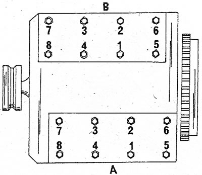
3.146 Sequence of an inhaling of bolts of fastening of a head of cylinders. in the head «A» cylinders 1 to 3 are located; in the head «IN» - from 4 to 6
147. Then, in the same sequence, tighten the bolts with a tightening torque of 60 Nm.
148. Loosen bolt no. 1 and re-tighten to 20 Nm. Do the same with the remaining bolts of both cylinder heads, following the sequence.
149. To tighten the bolts to a certain angle, use the angle gauge Mot. 591-01. Slide the angle template onto the socket (wrench) and turn the key 106° (see illustration).
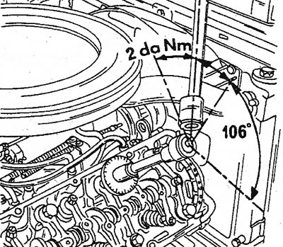
3.149 Angle of 106°to which the cylinder head bolts must be tightened after they have been tightened to 20 Nm
150. Thus tighten all bolts of fastening of a head of cylinders in the specified sequence.
151. The cylinder head bolts must be tightened after the engine has warmed up to operating temperature. The engine must be allowed to cool down for at least 6 hours and then the bolts are re-tightened when using the angle gauge. The additional rotation angle is 45°, i.e. half of a quarter of a full turn. Tighten the bolts in sequence without loosening them first. The cylinder head bolts do not need to be tightened after a certain mileage.
152. Install the oil pump switch, tensioner shoes, both tensioners, fixed damper bars, movable damper bars, and chain sprockets. The sprocket guide mark must point outward (see illustration).
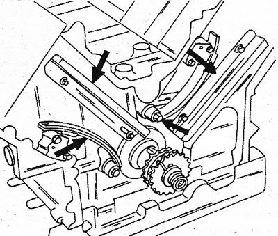
3.152 The arrows point to the bolts of the curves and straight rails
153. Adjust the valve clearances as described for the V6 engine.
154. Turn the crankshaft to the right until the middle of the segment key is in line with the left bank of cylinders.
155. Install the camshaft drive chain on the left drive sprocket so that the double sign in the chain is located above the sprocket mark.
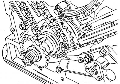
156. Put the camshaft drive chain on the inner crankshaft sprocket. Align the alignment mark at the front of the additional sprocket (see illustration).
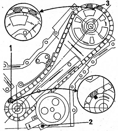
3.156 Left camshaft drive chain installed; 1. Mounting mark of the crankshaft sprocket; 2. Oil pump cover bolt; 3. Timing mark for camshaft sprocket
157. Install the sprocket on the camshaft. The dowel pin must fit into the chain sprocket.
158. Tighten the sprocket bolt to 75 Nm. The crankshaft must be blocked.
159. Install on the right side as follows:
160. Rotate the crankshaft 150°so that the alignment mark (1) was in line with the bottom bolt 1 (2) fuel pump covers (see illustration 3.156).
161. Install the chain on the camshaft sprocket. The additional chain alignment mark must be located above the sprocket alignment mark.
162. Install the camshaft drive chain on the crankshaft front sprocket.
163. A separate alignment mark in the chain must lie in line with the alignment mark of the chain drive sprocket. Both installed chains and alignment marks of chain sprockets are shown in the illustration.
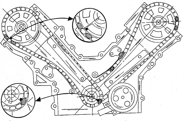
3.163 The front of the engine with the location of the alignment marks
164. Tighten the camshaft sprocket bolt to 75 Nm. Block the crankshaft.
165. To check the alignment marks, turn the crankshaft half a turn and make sure that the alignment mark on the sprocket of the cylinder bank «IN» (see illustration 3.146) stands in line with the mark on the crankshaft sprocket. Then rotate the crankshaft 90°and check that the alignment mark on the cylinder bank sprocket is «A» stands in line with the mark on the crankshaft sprocket.
166. Then turn the crankshaft further until the keyway on the end of the crankshaft appears at the top.
167. Install the chain tensioners by turning the locking mechanism with a screwdriver to the right. To do this, insert a screwdriver into the hole in the front of each tensioner.
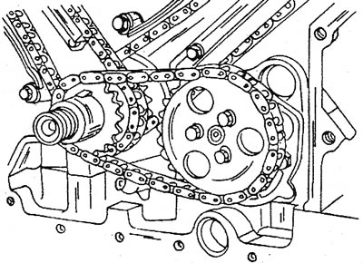
168. Rotate the crankshaft so that the key is at the top and install the oil pump sprocket gasket, key and sprocket (see illustration).
3.168 Details of the oil pump drive at the end of the crankshaft
169. Install the chain with the oil pump sprocket. Lubricate the sprocket bolts with special grease. The tightening torque is 6 Nm. The illustration shows the oil pump drive mechanism.
3.169 Oil pump drive
170. Install the camshaft drive cover gasket (dry), then install the camshaft cover on the two dowel pins and insert the bolts, the threads of which are lubricated with special grease. Trim the protruding edges of the gasket with a knife.
171. Drive a new O-ring into the camshaft drive cover and install the crankshaft timing belt pulley. Block the crankshaft (you can also pre-install the flywheel) and tighten the nut with a tightening torque of 180 Nm. Lubricate the thread of the nut with special grease.
172. The rest of the installation is carried out in reverse order.
173. Inject some oil through the hole (1) (see illustration), to provide initial lubrication to the oil pump when starting the engine. Then install the oil filter. Tighten the filter by hand until it contacts the lubricated rubber ring and tighten it further from this position by 1/8 to 3/4 turn.
3.173 Before installing the oil filter, fill it with engine oil through the hole «A»
174. Attach the flywheel or drive pulley. The bolts need to be changed every time as they cannot be reused. Tighten the flywheel bolts to 45 Nm and the drive pulley bolts to 65-75 Nm.