
Disassembly - general description
Thoroughly clean the external surfaces of the engine before starting work. Close all engine openings with clean rags in advance to prevent foreign bodies from entering inside the engine.
Engine disassembly will be described in detail later. In addition, work is described that can be carried out either with the engine installed or with the engine removed.
Avoid confusion of details. Bearing surfaces must never be scratched or beaten. Many parts are made of aluminum alloy and therefore require careful handling.
If it is necessary to use a mallet to separate certain parts, it is recommended to use a rubber or plastic one. Disassembly will be greatly facilitated if you use an assembly stand. Otherwise, place the engine on a workbench and secure it on both sides.
The description of the different engine groups is given separately. It should be mentioned that the turbocharged diesel engine is built on the basis of a 4-cylinder gasoline engine, i.e. the lower part of these engines is the same.
The disassembly of the engine is carried out in the specified sequence, however, if desired, it can be changed.
1995/2165 cc engines3 (J6R/ J7R/J7T)
1. Remove the alternator with console, ignition distributor, oil filter and hydraulic switch, fuel pump with intermediate flange (carbureted engine), the oil pump drive guard and the timing belt guard. Remove the mounting bracket.
2. Remove the intake and exhaust manifolds.
3. Remove the toothed belt as described later.
4. Use a center punch to mark the clutch and flywheel, then loosen the connecting bolts evenly in diagonal sequence. Remove flywheel. Note that the flywheel bolts of certain engines are blocked by lock washers.
5. Turn away a cover of a head of the block of cylinders and remove collars of a hose between the case of the thermostat and the water pump. Disconnect the hose.
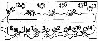
6. Turn out bolts of fastening of a head of the block of cylinders in sequence opposite to the specified (see illustration). Bolt marked with a letter «A» just relax (see illustration). This bolt will be the dowel pin.
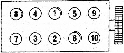
2.6a The sequence of tightening the bolts for fastening the cylinder head of engines of type «3». Loosen bolts in reverse order
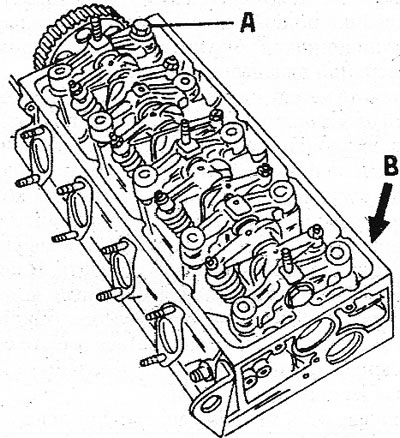
2.6b Bolt (A) fixing the cylinder head in its position can rotate the head during removal. It is necessary to hit the mallet in place (IN) to free the head
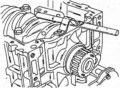
7. Before removing the cylinder head, rotate the cylinder block around the loose bolt (see illustration 2.6b). To do this, pull on one side of it, pressing on the second (with which bolt). If necessary, hit with a rubber mallet on the opposite corner of the head, indicated in the illustration by the letter (IN). As a result, the cylinder liners do not remain in the head, as could happen if the head were raised immediately. Finally, unscrew the last bolt and remove the head. Remove the cylinder head gasket and clean the surface of the seal residue.
8. Use the special tool to block the cylinder liners (see illustration). If not available, large washers, bolts and appropriate spacers can be used (length 135 mm), to lock the sleeves in their original position.
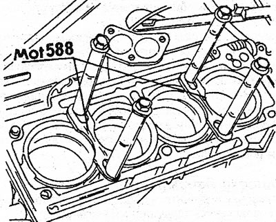
2.8 Locking pins must be used to hold the cylinder liners until the crankshaft is removed
9. Remove the water pump pulley and the pump itself.
10. Remove the toothed drive belt tensioner and idler gear with slotted key. On the other side of the engine, remove the intermediate shaft guard.
11. Remove the ignition distributor drive gear. To do this, insert a wooden object into the gear hole and put the gear on it. Pull the gear off the shaft. Now you can pull out the intermediate shaft.
12. Turn the engine over with the crankcase up.
13. Remove the oil pan, remove the gasket and unfasten the oil pump from the bottom surface of the crankcase. The oil pump is guided by dowel sleeves and must therefore be removed.
14. Establish the block of cylinders so that to provide access to a cranked shaft. Check the markings on the main bearing caps and connecting rod caps. If you are not sure, mark the covers with paint or mark them so that they can be accurately installed in their original place during assembly. Bearing #1 is at the end of the crankshaft facing the flywheel; The connecting rod bearing markings are located on the intermediate shaft. Paint or carefully scratch the cylinder number on the piston crown.
15. Turn away nuts of fastening of covers of rods. Remove the bearing caps and take out the liners. Place the bearing shells together with the covers. The lower and upper liners are labeled.
16. Insert a wooden plate between one of the counterweights of the crankshaft and the wall of the cylinder block, unscrew the sprocket bolt and remove it. Notice both dowel pins in the sprocket. Delete (with the help of pliers) segment key from the crankshaft and spacer. Never try to remove the gasket together with the crankshaft sprocket, as the segment key interferes with this. If the vehicle is equipped with an air conditioner, the compressor drive belt pulley (pulley is built-in) can be removed together with the crankshaft sprocket. The illustration shows the parts at the end of the crankshaft.
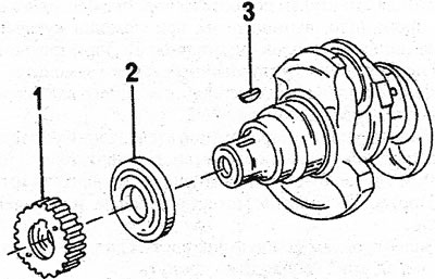
2.16 Crankshaft drive gear (1) and spacer (2) must be removed individually, as the segment key (3) prevents the gasket from being removed
17. If the flywheel has not yet been removed, this can be done now (if there is a lock washer, loosen it first). Flywheel bolts without a lock washer are self-locking and must always be replaced. '
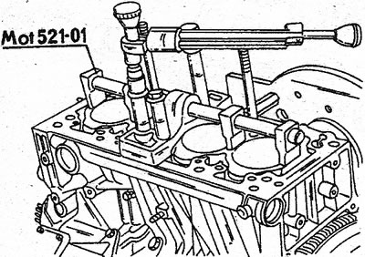
18. Compare marking of covers of radical bearings with data of the block of cylinders and if necessary sign details. Bearing #1 is on the flywheel side. The main bearing caps can then be removed, however note that the two caps have a tight fit (#1 and #5). It is best to mount a metal bar into the bearing cover for this (see illustration) and press the corresponding bearing cap with a steel rod.
The metal bar must be strong enough. Loosen the bolts of the remaining covers one by one and remove them together with the bearing shells. Keep the bearing shell with its cap together in case the shell is to be installed again.
2.18 Remove bearing caps #1 and #5 as shown if they are stuck
19. Carefully remove the crankshaft and remove the remaining bearing shells from the crankcase. Group the inserts with the covers so as not to be confused during installation. Also remove the thrust washers that regulate the axial clearance of the crankshaft.
20. Remove the blocking pins of the cylinder liners and remove the liners with pistons and connecting rods from the cylinder block in turn, as an assembly.
Turbocharged diesel engine
21. Remove all external parts of the engine, i.e. fuel pump and related parts, oil separator, intake and exhaust manifolds, fuel supply and return lines, engine mount, turbocharger, etc.
22. Drain engine oil and remaining coolant.
23. Tilt the clutch and flywheel and loosen the connecting bolts evenly in a diagonal sequence. Remove the clutch together with the friction disc.
24. Remove the toothed drive belt.
25. Bolts of fastening of a head of the block of cylinders loosen in sequence opposite to the specified (see illustration).
2.25 The sequence of tightening the cylinder head bolts of a turbocharged diesel engine. Loosen bolts in reverse order
26. Do the following (see illustration):
- A) Loosen and remove bolts (1) and nuts (2), except for the bolt (A). Loosen this bolt like the others, but do not remove it completely.
- b) Tap with a wooden mallet on all sides of the cylinder head so that you can roll it out of the way, leaving it on the bolt. Never attempt to lift the cylinder head up. As a result, the sealing rings of the cylinder liners can be damaged, small parts of which fall into the crankcase.
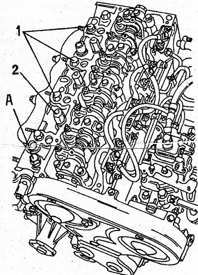
2.26 Removing the cylinder head of a turbocharged diesel engine. Numerical and letter designations are mentioned in the text
27. Remove the cylinder head gasket and clean the sealing surface.
28. Remove from a head of the block of cylinders of rockers.
29. Install a special tool or similar fastener on the cylinder head (see illustration). In this way, the liners will be held in the cylinder bores.
2.29 Cylinder liner locking device for turbocharged diesel engine
30. Remove the water pump pulley and the pump itself.
31. Turn away tension devices of a gear drive belt and a pulley of an intermediate shaft. Remove the key from the intermediate shaft. Remove the intermediate shaft cover from the cylinder block.
32. Remove the brake booster vacuum pump with the oil pump roller.
33. Turn the engine over onto the cylinder block and remove the oil pan. Remove the seal. Remove the oil pump. The pump is held in position by mounting sleeves.
34. The rest of the work is carried out in the same way as described for gasoline engines.
V-shaped 6-cylinder engine (Z7W)
35. Screw on the clutch and flywheel and loosen the connecting bolts evenly. Remove clutch and friction disc. On vehicles with automatic transmission, the drive plate is removed in a similar way. The flywheel or drive plate must be locked.
36. Turn away a nut of a pulley of a gear drive belt.
37. Remove the oil pump cover and remove the oil seal. You can use a punch to remove the seal.
38. Remove the oil filter. Use a filter remover if possible.
39. Remove the oil level indicator and indicator guide tube.
40. Remove the generator with bracket, ignition distributor, intake manifold with fuel injection system components and all parts on the outside of the engine.
41. Remove the water pump and its hoses.
42. Press the crankshaft timing belt pulley with the help of two mounting blades installed under it.
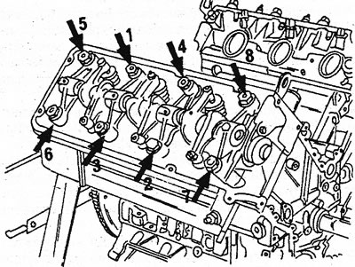
43. Turn the crankshaft so that the key is at the top, and remove the camshaft drive cover along with the gaskets. The top left cover on the engine can be removed. Remove sealing ring and discard (see illustrations).

2.43a Engine front components
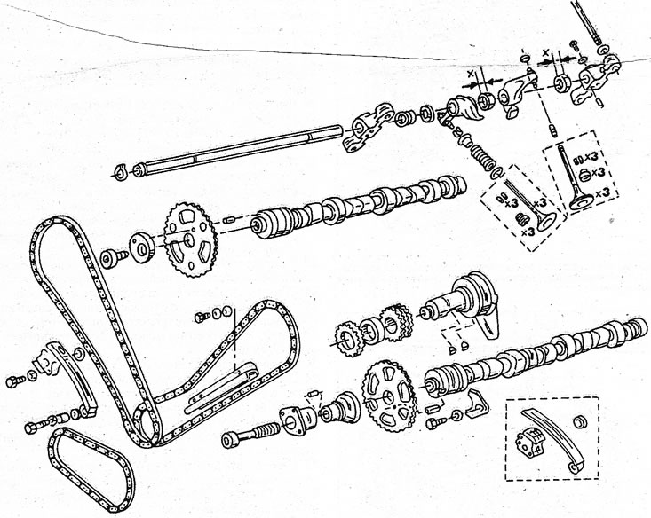
2.43b The location of the camshaft, valves and rocker arms in the V6 engine
44. Remove the cylinder head covers.
45. Remove the oil pump sprockets along with the chain. The oil pump sprocket is attached with three screws (see illustration). Remove the chain with both sprockets. Under the sprocket is the oil pump, which can be removed by unscrewing the four bolts.
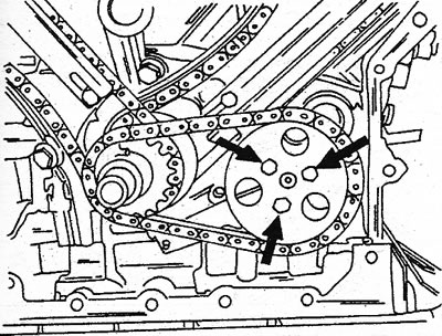
2.45 Oil pump sprocket bolts
46. Turn away bolts of both asterisks of a crankshaft. The crankshaft must be blocked. For example, slide a square rod between the chain and the camshaft sprocket. To unscrew the bolt, use a 10 mm hex wrench (see illustration). When removing parts, note which side of the engine they belong to.
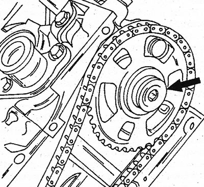
2.46 Camshaft sprocket bolt. It's a socket bolt
47. Reduce tension on both chain tensioners. To do this, insert a screwdriver into the hole in the end of the tensioner and turn the locking mechanism a quarter of a turn (see illustration). Then press the shoe with your finger, as shown in the illustration. Loosen both bolts and remove tensioner. First you need to remove the tensioner on the right. Under the tensioner is a strainer, which also needs to be removed. Camshaft sprockets and chains (right first) can now be removed.
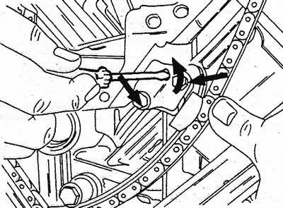
2.47 To loosen the chain tensioner, turn the lock pin, a quarter of a turn to the left, and then remove both bolts
48. Remove the bent and straight chain guides after the fasteners have been dismantled.
49. Fill the space below the crankshaft sprocket with rags so that the keys do not fall into the crankcase during the following work. Pull the sprocket off the crankshaft with your hands. If it sits very firmly on the shaft, use a two-legged puller. Remove the extra sprocket underneath in the same way. In both cases, remove the keys from the shaft.
50. Lay the cylinder block on its side so that the right row of cylinders is on top, and remove the rocker shaft. Since each rocker shaft is only suitable for its own cylinder head, they must be marked before removal «rights.» and «a lion.». Loosen the rocker bolts, following the removal sequence (see illustration), because the bolts are also attached to the cylinder head. The figure shows the left cylinder head. The order in which the bolts are removed is the same as for the right cylinder head.
2.50 The sequence of loosening the bolts of the left cylinder head
51. Drive round metal pins into the holes (A) And (IN) (see illustration). The pins should be directly against the dowel pins. Carefully drive the dowel pins into the cylinder head.
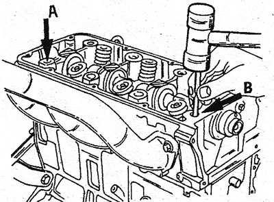
2.51 in holes (A) And (IN) using a mallet, dowel pins are driven in
52. Lightly tap the cylinder head with a rubber or plastic mallet and, as soon as the head is released, lower it from top to bottom. Remove the cylinder head gasket.
53. In order for the liners to remain in the cylinders, they must be secured. To do this, use the locking pins again, as described earlier. Never turn the cylinder block without blocking the cylinder liners.
54. Turn the engine so that the left row of the cylinder head is at the top, and remove the left cylinder head as described above.
55. If the pistons and connecting rods must be removed, mark the bottoms of the pistons. It is recommended to mark the pistons with arrows pointing outwards. Also on the bottom, the cylinder number is carefully scratched or written with paint. The crankcase is disassembled as follows:
56. Remove the oil pan and oil receiver screen.
57. Turn the engine over and remove the oil pan bolts. Remove the oil pan along with the seal.
58. Turn out three bolts fastening a grid of an oil receiver, and take out a grid. Remove the oil pickup tube rubber ring.
59. Remove the metal rim of the oil receiver mesh (remove two screws on one side, one on the other).
60. Remove the crankcase.
61. Remove all bolts at the bottom of the crankcase, remove the eight large nuts in the middle (for main bearings) and disconnect the crankcase from the cylinder block.
62. Remove the rubber ring from the lubrication channel.
63. Both upper bearing caps should remain in this position. To do this, use bushings that need to be inserted over the studs and secured with a nut and washer. Otherwise, this operation can be carried out using a special tool (see illustration); metal bridges are screwed to the crankcase. Both middle bearing caps can be locked with nuts.
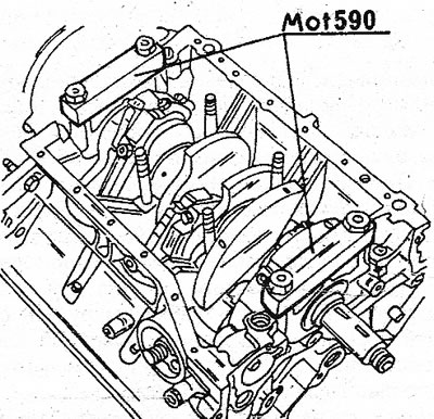
2.63 The front and rear main bearing caps are secured against falling out by means of two connecting bridges. This keeps the crankshaft
64. Pistons and connecting rods are removed as follows:
65. Check up marking of rods and their covers. If there are no marks, connecting rods and caps can be scored. Connecting rod bearing #1 is located at the end of the crankshaft on the flywheel side. The serial numbers of the cylinders are the same for both the right and left sides.
66. Loosen both nuts of each connecting rod bearing in turn and remove the bearing caps. Remove the earbuds and set them aside with the lid.
67. Using a hammer handle, push the piston out of the cylinder liner and grab it with your hand from the other side. Remove the bearings from the connecting rod and immediately install the cap with both bearings into the corresponding connecting rod.
68. Remove all connecting rods and pistons in the same way.
69. After removing the pistons and connecting rods, number the cylinder liners in accordance with the cylinder number and, after removing the connecting bridges, remove the liners from the cylinders: The crankshaft is removed as follows:
70. Remove the crankshaft rear oil seal cover (see illustration), if it has not already been done, and immediately remove the O-ring.
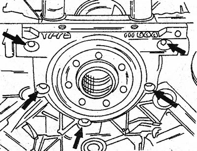
2.70 Rear flange O-ring bolts are at the indicated points
71. Remove the bridges of the front and rear bearings and unscrew the nuts from the studs of both middle bearings. The covers are marked starting at the rear of the engine with numbers 1 to 4 and cannot be interchanged.
72. Remove the thrust washers for adjusting the crankshaft axial clearance from the rear bearing. In this case, the upper half of the washer can be removed. To remove the lower half, slide one of its upper edges down with a screwdriver until the second one comes out from the opposite side.
73. Take the crankshaft at both ends and remove from the cylinder block.
74. Take out bowls of radical bearings from the block of cylinders and put them together with covers of bearings and loose leaves which are there.