



Contents: Flushing 🠛 Camshafts 🠛 Cylinder head 🠛 Cylinder block 🠛 Hydraulic compensators 🠛 Valves 🠛 Valve guide bushings 🠛 Valve springs 🠛 Pistons 🠛 Checking clearances in piston ring…🠛 Crankshaft 🠛 Cylinder block 🠛
Before disassembling, all auxiliary units and assemblies are removed from the engine, and only then is it completely disassembled. The order of removing auxiliary units is approximately as follows:
- air conditioning compressor;
- power steering pump;
- generator assembly with mounting bracket;
- starter;
- engine management system;
- electrical wiring harnesses;
- intake and exhaust manifolds;
- oil dipstick;
- engine mounts;
- flywheel or faceplate (if there is an automatic transmission).
For major repairs, the following are removed from the engine:
- cylinder head;
- engine oil pan;
- oil pump;
- water pump;
- pistons with connecting rods;
- crankshaft.
The engine assembly is carried out in the reverse order to that listed.
The processes of disassembling and assembling complex engine units will be discussed in the relevant subsections.
Before disassembling, prepare small boxes or containers to place the small parts you are removing. This will help preserve them during subsequent assembly. After removing each part, reinstall the fasteners in their places (bolts, nuts, washers), to speed up the assembly process and preserve the threads on the parts. Keep the parts to be replaced so that you can compare them with the new ones. Mark the position of the parts to be removed (with paint, a line or other means), so that they can be installed in their original place during assembly. Before disassembling, thoroughly wash the engine outside with kerosene.
Place the clean engine on a disassembly stand.
1. Remove: - plugs on the ends of the camshafts;- the plug of the TDC position lock hole.
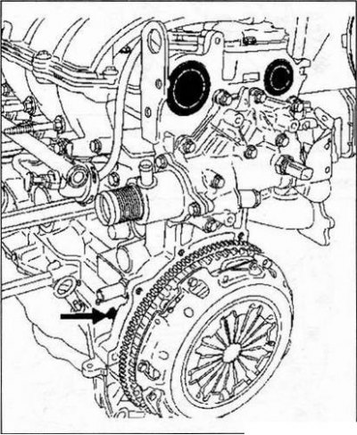
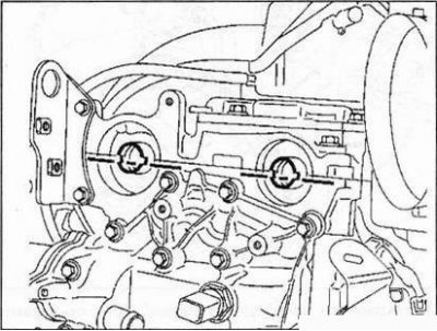
2. Install the camshafts with the grooves facing down as shown in the figure below.
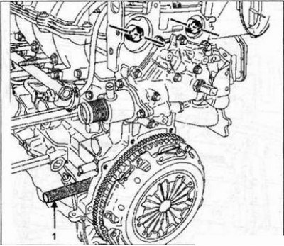
4. Turn the engine crankshaft counterclockwise (from the valve timing side), until the crankshaft rests against the TDC locking rod.
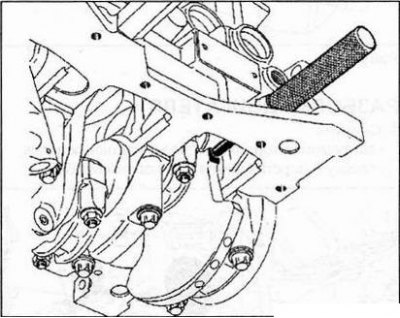
The grooves at the ends of the camshafts must be horizontal and offset downwards relative to the axis, as shown in the figure.
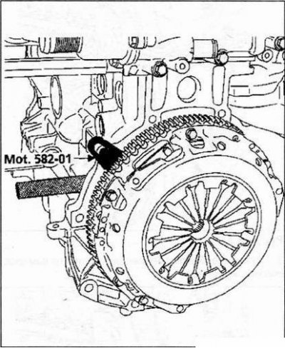
5. Install the flywheel locking device (Mot. 582-01).
6. Remove:
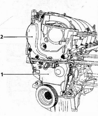
- crankshaft pulley for auxiliary equipment drive;
- middle cover of the timing drive (1);
- upper cover of the timing drive (2).
7. Unscrew the nut (3) on the tension roller.
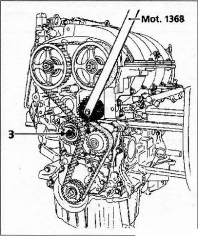
8. Remove the idler pulley using tool Mot. 1368.
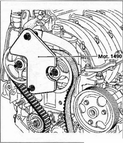
9. Remove: timing belt; camshaft pulleys using tool Mot. 1490.
10. Remove the parts shown in Figures 1-12.
Loosen the air filter housing mounting bolts and remove the air filter housing.
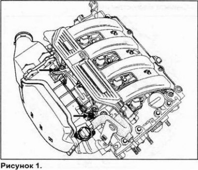
Remove the two throttle body mounting bolts and remove the intake air distribution manifold.
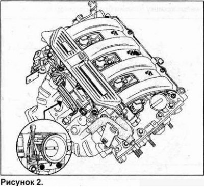
Remove the ignition coils.
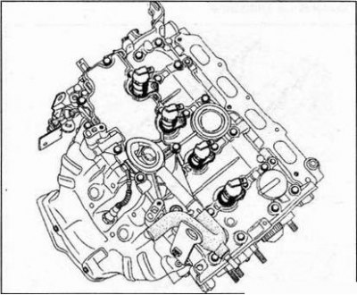
Figure 3. |
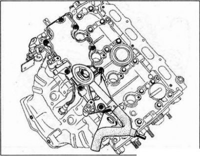
Figure 4. |
Unscrew the 24 cylinder head cover mounting bolts and then, tapping the projections (1) with a copper hammer, remove the cylinder head cover vertically upwards.
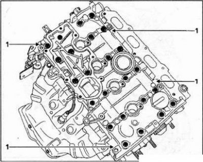
Figure 5.
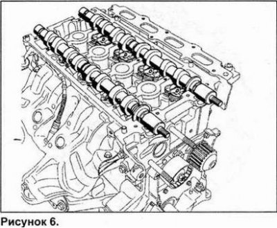
Remove the intake and exhaust camshafts.
Remove the rocker arms and hydraulic lifters.
Caution: Place the hydraulic lifters in a vertical position to prevent oil leakage from them.
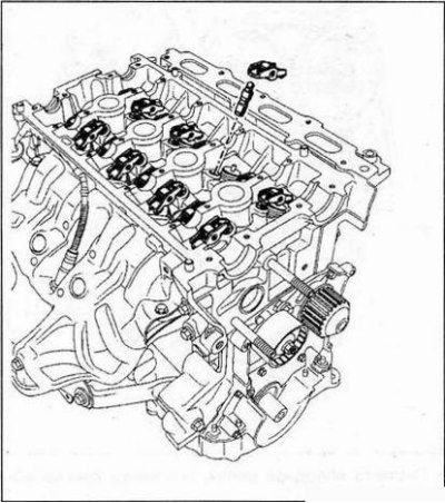
Figure 7.
Loosen the two bolts securing the catalytic converter brace and remove the catalytic converter brace (see fig. 8).- Using tool Mot. 1495, remove the oxygen sensor; remove the exhaust manifold heat shields and the inner timing case spacer (see fig. 8).
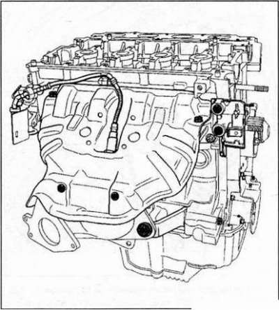
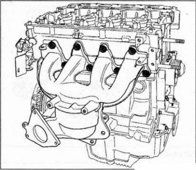
Figure 9.
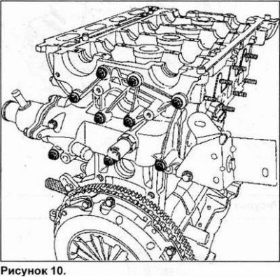
Remove the removable part of the cooling jacket at the end of the cylinder head.
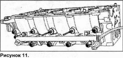
Remove the fuel distribution rail.
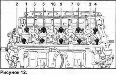
Loosen the 10 cylinder head mounting bolts evenly, in several passes, in the sequence shown in the figure. Remove the cylinder head and cylinder head gasket.
11. Using a valve puller, compress the valve springs.
12. Remove: valve spring crackers; upper valve spring plates; valve springs; valves; valve guide oil seals using pliers Mot. 1335.
13. Remove the clutch housing and driven disc.
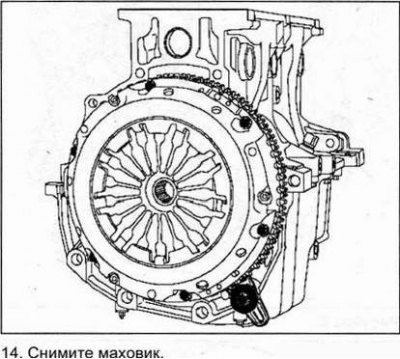
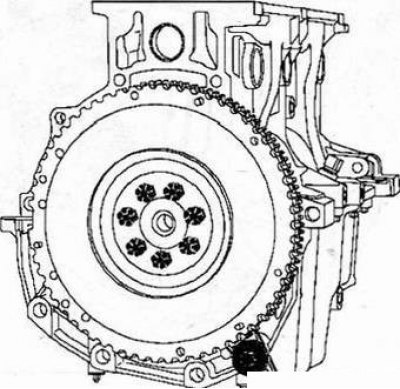
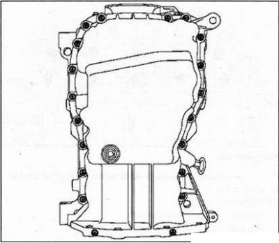
Figure 1.
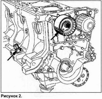
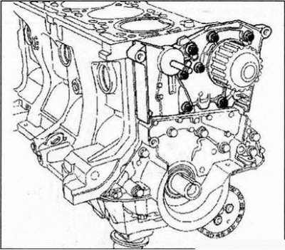
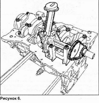
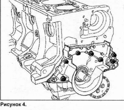
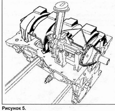
Caution: To avoid cracking the connecting rods, do not use a center punch to mark the big end caps relative to the connecting rods. Use a permanent marker for this purpose.
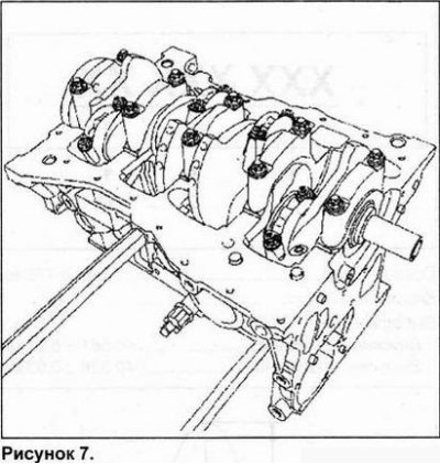
Remove the crankshaft bearing caps (they are numbered 1 through 5).
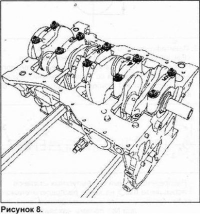
Note: It is very important to mark the position of the crankshaft bearings as they may be of different size groups for each bearing.
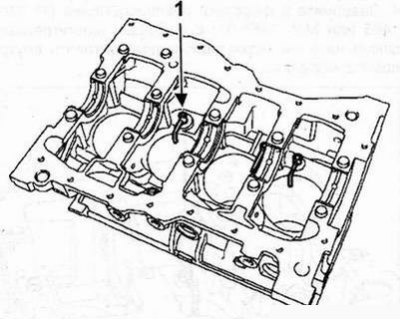
Removing the piston bottom cooling nozzles. Drill out the piston bottom cooling nozzles (1) using a 7 mm drill.
2. Remove: spring thrust bushing (1); spring (4).
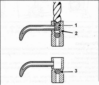
Caution: Do not remove the ball (3) to prevent chips from entering the oil channel.
3. Remove metal filings with a brush.
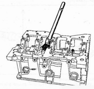
4. Screw the device (1) into the injectors (Mot. 1485 or Mot. 1485-01) using a 6mm Allen key (the key must be inserted inside the device).
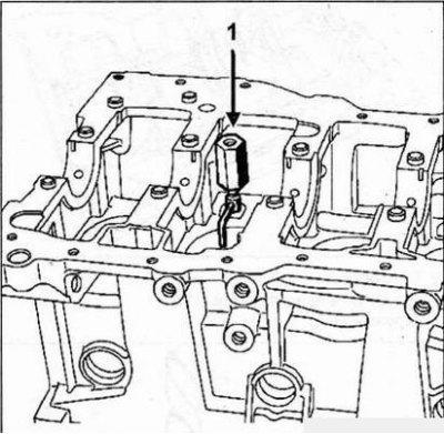
5. Screw the inertia puller (1) (Emb. 880) onto the tool (Mot. 1485 or Mot. 1485-01).
6. Remove the injectors.
Flushing
It is very important to prevent damage (scratches, nicks) on the mating surfaces of aluminum parts.
To remove any remaining old gasket from the surface, use the special Decapjoint solvent.
Apply this solvent to the area to be cleaned, wait for about 10 minutes, and then remove the remaining gasket with a wooden spatula.
Camshafts
1. The camshafts are identified by marking (A).
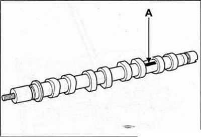
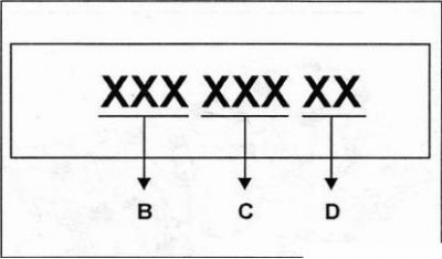
Marking details (A):
- - marks (B) and (C) are intended for the supplier only;
- mark (D) is used to identify the camshafts: AM - intake camshaft; EM - exhaust camshaft.
- Axial clearance - 0.08 - 0.178 mm
- Number of supports - 6
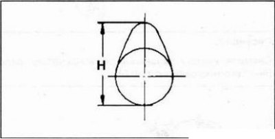
- Height of cams "H":
- Intake valves - 40.661 ±0.03 mm
- Exhaust valves - 40.038 ±0.03 mm
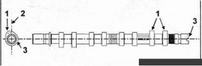
2. Identification by cam lobe position. - Inlet camshaft. Position groove 3 on the end of the camshaft horizontally and offset downwards. Cam lobe 1 of cylinder #1 should be to the left of vertical axis 2.
Exhaust camshaft. Position groove 3 at the end of the camshaft horizontally and offset downwards. Cams 2 of cylinder No.1 should be to the right of vertical axis 1.
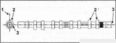
Table. Diameter of camshaft bearings in cylinder head
| From the flywheel side of the engine | |
| 1 | |
| 2 | |
| 3 | 25+0.061+0.04 mm |
| 4 | |
| 5 | |
| 6 | 28+0,061+0.04 mm |
| From the timing drive side | |
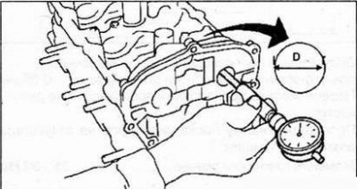
Checking the diameters of the camshaft supports in the cylinder head.
Table. Camshaft journal diameters
| From the flywheel side of the engine | |
| 1 | |
| 2 | |
| 3 | 25°-0.021 mm |
| 4 | |
| 5 | |
| 6 | 28°-0.021, mm |
| From the timing drive side | |
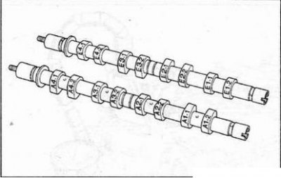
A 4 -1 = Inlet valve of cylinder 4 and cam No.1.
E 4 -1 = Exhaust valve of cylinder 4 and cam No.1.
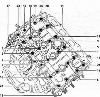
Checking the axial play of the camshaft. Install: - camshafts in the correct position;- cylinder head cover; tighten the bolts that secure it (for the tightening order and torques, see the table "Tightening order of the cylinder head cover bolts").
Check the axial clearance, which should be within 0.08-0.178 mm.
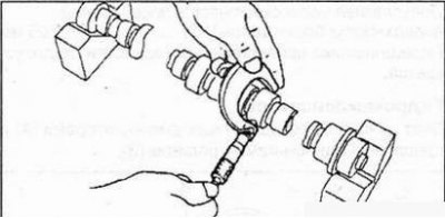
Checking the diameters of the camshaft bearing journals.
Table. Cylinder head cover bolt tightening sequence
| Stage | Bolt tightening sequence | Sequence of loosening bolts | Tightening torque (Nm) |
| №1 | 22-23-20-13 | - | 8 |
| №2 | from 1 to 12, from 14 to 19, from 21 to 24 | - | 12 |
| №3 | - | 22-23-20-13 | - |
| №4 | 22-23-20-13 | - | 12 |
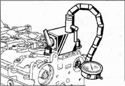
Note: To fit the magnetic indicator holder to the cylinder head, use tool Mot. 588 and secure it using the oil sump mounting bolts (1) and bushes (2) with the dimensions shown below:
- outer diameter 18 mm;
- diameter of the hole for the bolt (1) 9 mm;
- height 15 mm.
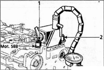
Remove the cylinder head cover and camshafts again.
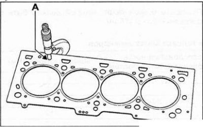
Cylinder head gasket. The thickness of the cylinder head gasket is measured at point (A).
Cylinder Head Gasket Thickness:
- The thickness of the new sealing gasket is 0.96 ±0.06 mm
- Thickness of the compressed gasket - 0.93 ±0.06 mm
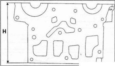
Cylinder head
Height "H" of the cylinder head - 137 mm
The permissible non-flatness of the mating surface of the cylinder head is 0.05 mm.
Regrinding of the mating surface is not permitted. Check the cylinder head for possible cracks.
Tightening torques for spark plugs: 25-30 Nm
Cylinder block
Check the non-flatness of the mating surface using a straightedge and a set of feeler gauges.
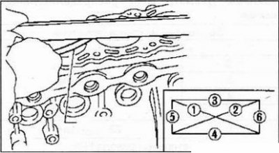
The permissible non-flatness of the mating surface of the cylinder block is 0.03 mm.
Regrinding of the mating surface is not permitted.
Hydraulic compensators
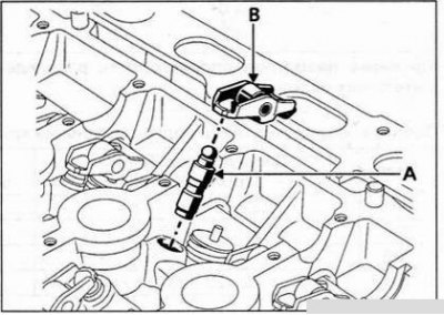
This engine is equipped with hydraulic lifters (A) and single-arm roller levers (B).
Valves
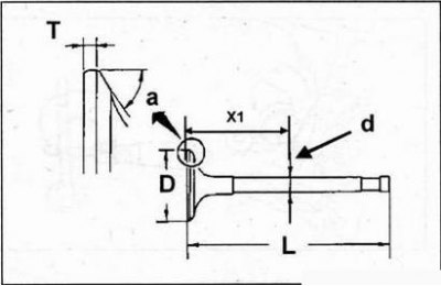
Valve lift:
- Inlet valve - 9.22 mm
- Exhaust valve - 8.075 mm
Rod diameter "d" (measured at distance "X1"):
- X1 (inlet valve) — 75.14 ±0.35 mm
- Inlet valve - 5.484 ±0.01 mm
- X1 (exhaust valve) — 77.5 ±0.35 mm
- Exhaust valve - 5.473 ±0.01 mm
Plate diameter "D":
- Inlet valve - 32.7 ±0.12 mm
- Exhaust valve - 27.96 ±0.12 mm
Chamfer angle:
- Inlet and outlet valves - 90°15'
Valve length "L":
- Inlet valve - 109.32 mm
- Exhaust valve - 107.64 mm
Thickness of the head "T":
- Inlet valve - 1.15 mm
- Exhaust valve - 1.27 mm
Valve seats
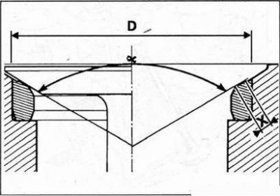
Seat seat chamfer angle α:
- Inlet and outlet valves - 89°
Width of the landing chamfer X:
- Inlet valve - 1.3+1,4 mm
- Exhaust valve - 1.4+1,3 mm
Outer diameter D:
- Inlet valve - 33.542 ±0.006 mm
- Exhaust valve - 28.792 ±0.006 mm
Valve guide bushings
Length:
- Inlet and outlet valves - 40.5 ±0.15 mm
Outer diameter of guide bushing:
- Inlet and outlet valves - 11+0,068+0,05mm
Inner diameter of guide bushing:
- Inlet and outlet valves:
- Unprocessed - 5+0,075 mm
- Processed* - 5.5+0,018 mm
* The hole in the guide bushing is reamed to the specified size after pressing the bushing into the cylinder head. Diameter of the socket for the guide bushing in the cylinder head:
- Inlet and outlet valves - 11 mm
Oil scraper caps are installed on the guide bushings of the intake and exhaust valves (valve stem seals), simultaneously serving as lower supports for the valve springs.
Inlet and outlet valve guide angles: Inlet valve - 63°30'
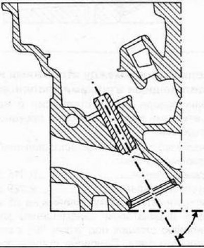
Exhaust valve - 66°
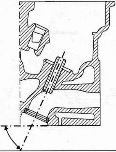
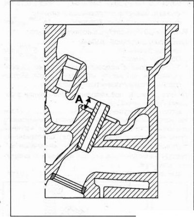
Protrusion "A" of the guide bushings of the intake and exhaust valves - 11 ±0.15 mm
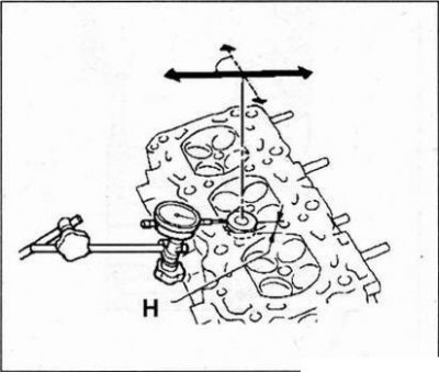
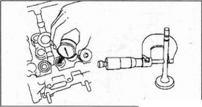
Checking the clearance between the valve stems and valve guides. There are two ways to check the clearance between the stems and valve guides.
Nominal clearance between valve guide and valve stem:
- Inlet valve - 0.015 ±0.048 mm
- Exhaust valve - 0.029 ±0.062 mm
1. Raise the valve head by 25 mm, then measure the valve movement with an indicator in the direction of the arrows at an angle of 90° to the camshaft axis. Half of the obtained value will give the value of the gap between the stem and the valve guide.
2. Measure the valve stem diameter and the inside diameter of the valve guide.
Valve stem sealsTo install the valve stem seals, use the Mot. 1511 tool.
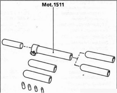
Note: Do not coat the valve stem seals with oil before installation.
Installing new valve stem seals. Insert the valve into the cylinder head.
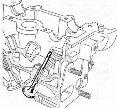
Place the Mot. 1511 tip on the valve stem (the inner diameter of the tip must be equal to the diameter of the rod).
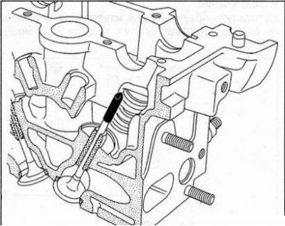
Hold the valve against the seat. Install the valve stem seal (not oiled) on the tip
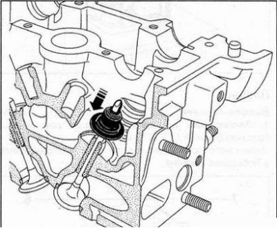
Press the oil seal until it comes off the tip, then remove the tip.
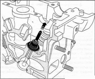
Install the push rod (1) onto the valve stem oil seal.
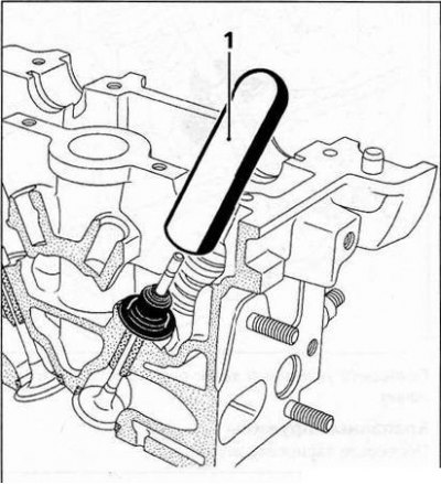
Note: The inside diameter of the tappet should match the diameter of the valve stem. In addition, the bottom of the tappet should partially rest against the valve stem oil seal, which serves as the lower support washer for the valve spring.
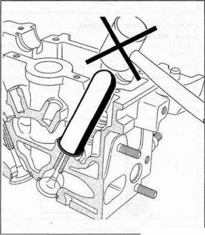
Replace the oil seal by tapping the top of the tappet with the palm of your hand until the oil seal contacts the cylinder head.
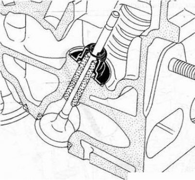
Repeat the above operations for all valves.
Valve springs
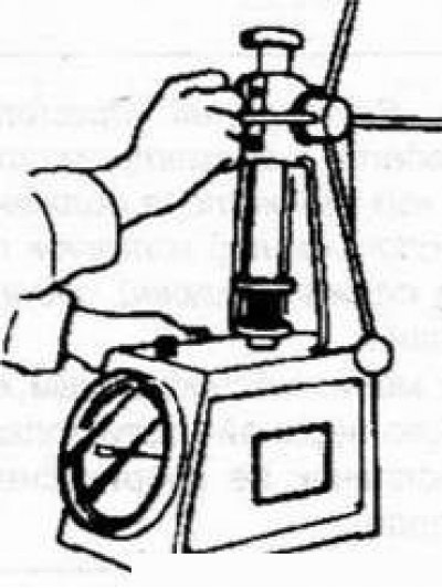
Check the spring calibration.
Length in free state - 41.30 mm
Length under load:
- 190 N - 34.50 mm
- 590 N - 24.50 mm
Length when fully compressed - 23.20 mm
Inner diameter - 18.80 mm
Outer diameter - 27 mm
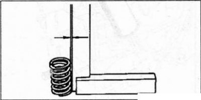
Permissible deviation of the spring from the vertical is 1.2 mm
Oval wire.
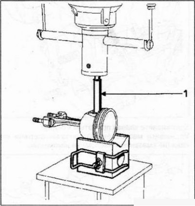
Removing the piston pins: Place the piston in the V-shaped stand so that the piston pin is aligned with the hole for its removal.
Using the mandrel (1) to extract the piston pin, remove it from the piston using a press.
Pistons
Piston height - 46.5 mm
1. Pressing in the piston pin using devices A13, C13 and B10. The pin is pressed into the connecting rod and rotated in the piston bosses.
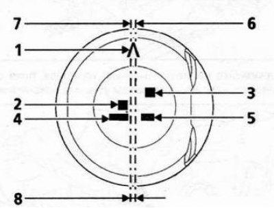
Piston marking. 1 - Piston orientation (mark "L" should be on the flywheel side of the engine), 2 - Used only by the supplier, 3 - Piston class (A-B-C), 4 - Used only by the supplier, 5 - Used only by the supplier, 6 - Piston symmetry axis, 7 - Piston pin hole axis, 8 - Offset between the axis hole (7) and the piston symmetry axis (6) - 0.8 mm.
Table. Dimensional groups of pistons and cylinders of the block
| Designation of piston size group | Piston diameter, mm | Cylinder diameter, mm |
| A | 79,470 - 79,479 | 79,500 - 79,509 |
| IN | 79,480 - 79,489 | 79,510 - 79,519 |
| WITH | 79,490 - 79,500 | 79,520 - 79,530 |
Attention: It is necessary to maintain the correspondence of piston and cylinder diameters.
The position of the "T" holes in relation to the joint surface of the cylinder block allows us to determine the size group for each cylinder and, consequently, the diameter of the corresponding piston (see the correspondence table below).
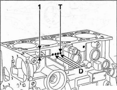
The marking zone includes: 1 - to indicate the size group (A, B or C), D - to correlate the size group with the cylinder number.
Table. Designation of size groups of block cylinders
| Positions of T holes | Size group |
| 1 = 17 mm | A |
| 2 = 27 mm | IN |
| 3 = 37 mm | WITH |
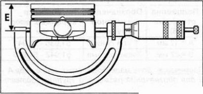
2. Measuring the piston diameter. The diameter measurement should be carried out at distance E.
- E — 45.7 ±0.01 mm
Checking clearances in piston ring locks
1. Install the piston ring (2) into the cylinder.
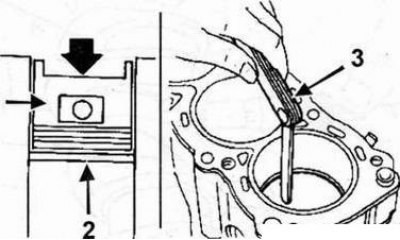
2. Push the piston ring (2) to the middle of the cylinder using the piston (1).
3. Measure the ring gap in the lock using a set of feeler gauges (3).
Table. Clearances in piston ring locks
| Piston rings | Gap in the lock |
| Upper compression ring | 0.225 ±0.075 mm |
| Lower compression ring | 0.5 ±0.1 mm |
| Oil scraper ring | 0.9 ±0.5 mm |
4. Replace the piston rings if the clearances are outside the tolerances. If the clearances remain outside the tolerances even with new rings, replace the cylinder block.
Crankshaft
Number of supports - 5
Main journals with fillet grooves: Nominal diameter - see table below
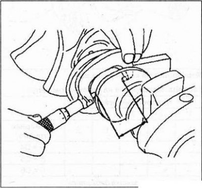
Crankshaft axial clearance: Without wear of the mounting bearing liners - 0.045-0.252 mm
Taking into account the wear of the mounting bearing liners - 0.852 mm
The mounting bearing shells are located on support No.3.
Note: The crankshaft crank radius is 35mm.
Connecting rod journals with fillet grooves: Nominal diameter - 43.97 ±0.01 mm
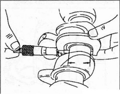
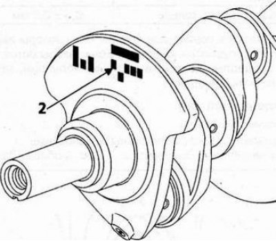
Marking on the crankshaft.
Table. Marking on the crankshaft
| no. of root neck | |||||
| V | 2 | 3 | 4 | 5 | |
| E | F | E | E | E | Size group |
| D = D4 | |||||
| E = D5 | |||||
| F = D6 | |||||
* From the engine flywheel side.
| Designation of the size group on the crankshaft | Main journal diameter, mm |
| D = D4 | 47,990 - 47,996 |
| E = D5 | 47,997 - 48,002 |
| F = D6 | 48,003 - 48,009 |
Cylinder block
The size groups of the main bearings (5) are indicated by the position of the holes on the cylinder block (6) above the oil filter.
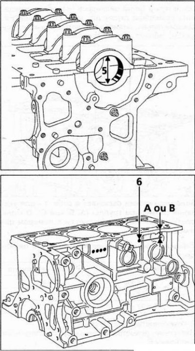
Table. Dimensional groups of main bearings
| Position of holes (6) | Size group designation | Main bearing diameter, mm |
| A = 17 mm | 1 or blue | 51,936 - 51,941 |
| B = 27 mm | 2 or red | 51,942 - 51,949 |
Note: The marking zone includes A B to indicate the size group, respectively, 1 or 2.
Table. Correspondence of dimensional groups of liners to dimensional groups of main journals and main bearings of the crankshaft
| Size group of molar necks | |||
| D1 or D4 | D2or D5 | D3 or D6 | |
| 1* | C1 = Yellow 1.949-1.955 | C2= Blue 1.946-1.952 | C4 = Red 1.953-1.959 |
| 2* | SZ = Black 1.943-1.949 | C1 = Yellow 1.949-1.955 | C2 = Blue 1.946-1.952 |
| Thickness and class of liners | |||
* Dimensional group of the crankshaft main bearing.
Note: The spare parts warehouse will only supply inserts of size group 02 (blue marks).