
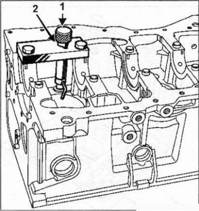
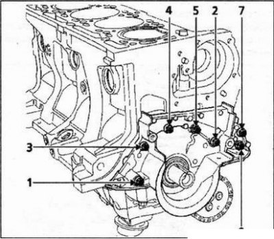
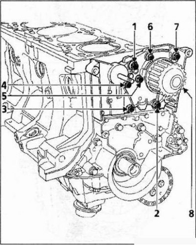
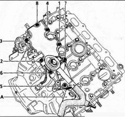
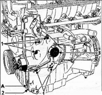
Installation of nozzles for cooling the piston bottoms
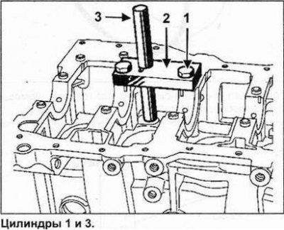
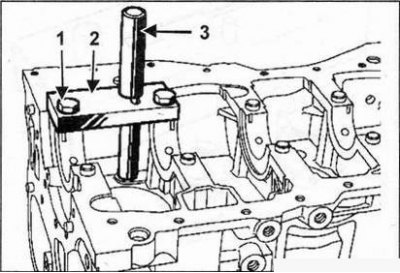
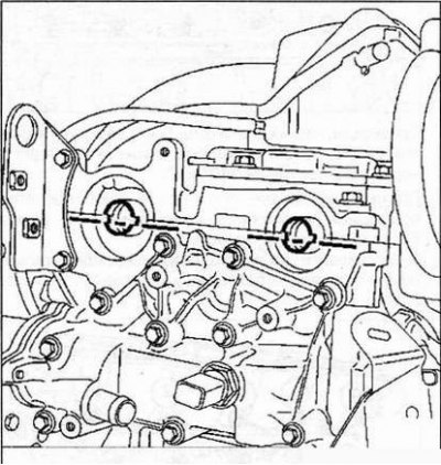
1. Install the plate on the block (2) accessories Mot. 1494 without tightening the two mounting bolts (1).
2. To center the plate, install the jig (3) into the plate (2) (the end of the conductor must enter the hole for the nozzle).
3. Tighten the two mounting bolts (1).
4. Remove the conductor.
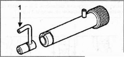
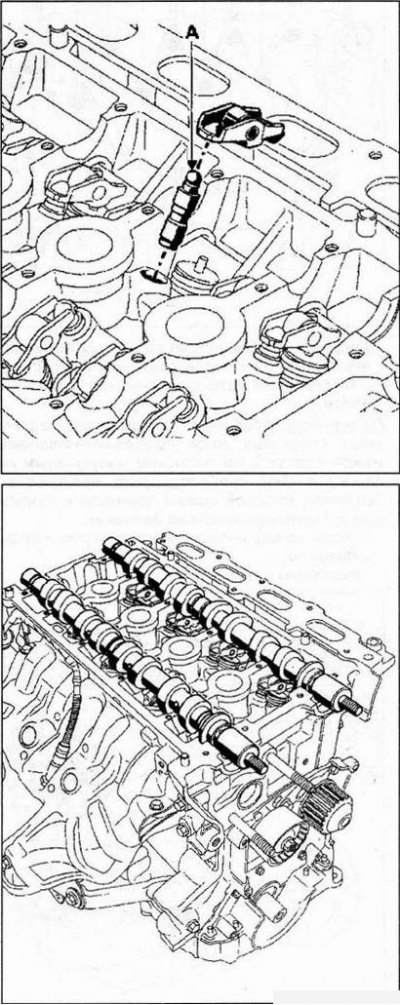
Attention! Pay attention to the installation direction of the injector. Tip (1) the injector should point towards the center of the cylinder.
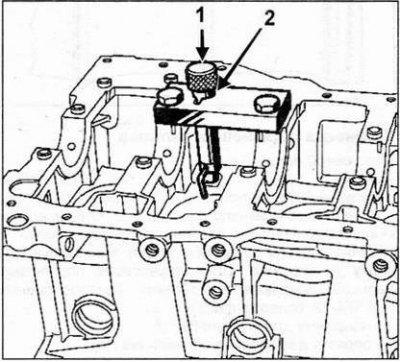
6. Install the mandrel instead of the jig.
7. Apply a few hammer blows to the mandrel until the shoulder touches (2) mandrels (1) with support.
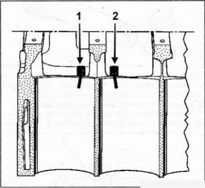
Cylinders 1 and 3.
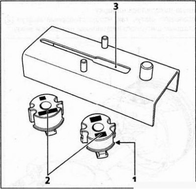
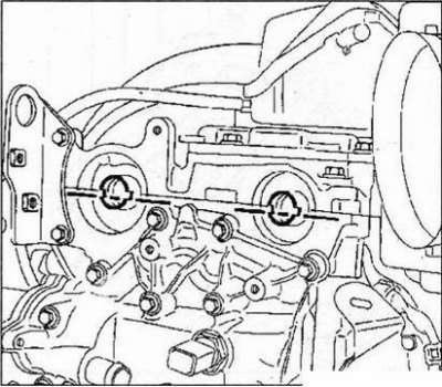
8. Check that the nozzles for cooling the piston heads are correctly oriented. Label (1) corresponds to the injectors of cylinders 2 and 4, mark (2) corresponds to the injectors of cylinders 1 and 3.
Piston pin installation
Piston pin:
- Length - 61.7-62 mm
- Outer diameter - 19.986-19.991 mm
- Inner diameter - 11.6 (Max) mm
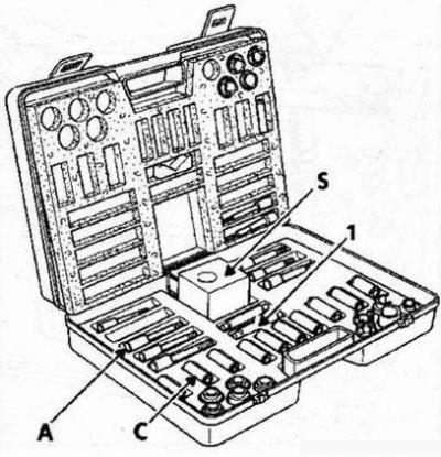
The piston pins are pressed tightly into the upper heads of the connecting rods and have a floating fit in the pistons. To press in the piston pins, use tool kit Mot.574-22 containing:
- piston stand (S);
- finger extractor (1);
- setting rods (A) with centering devices (WITH).
Connecting rod preparation
- Axial clearance of the connecting rod on the neck of the crankshaft - 0.31 - 0.604 mm
- The distance between the axes of the piston and crank heads of the connecting rod - 128 + 0.035 mm
- Diameter of the crank head of the connecting rod - 48.5±0.25 mm
- Connecting rod piston head diameter - 19.945 - 19.958 mm
Attention! Do not use a punch to mark the caps and connecting rods, as this may cause the connecting rod to begin to break. Use an indelible pencil.
By mass, the connecting rods of the same engine should not differ from each other by more than 6 grams.
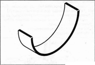
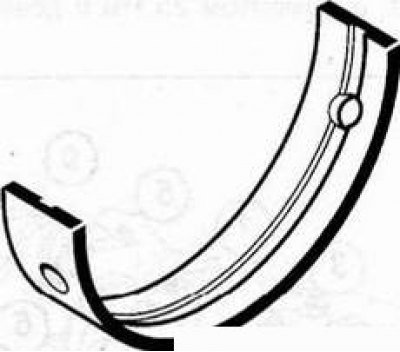
Connecting rod bearing shells
The engine is equipped with liners that do not have protection against incorrect installation.
The inserts are installed using tool Mot. 1492.
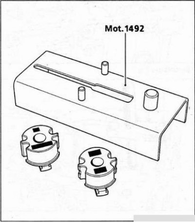
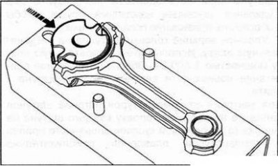
Installing the bushing in the crank head
1. Choose the correct liner holder for your engine (1) (see motor type marking (2) on holder).
2. Insert the earbud holder into the groove (3) device bases.
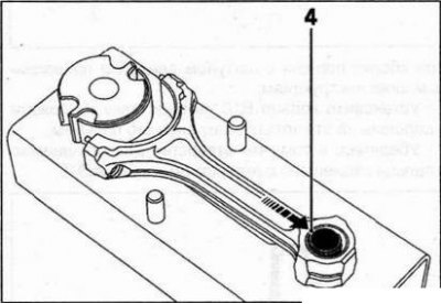
3. Put the crank on the base (as it shown on the picture). Make sure the bottom (4) piston head of the connecting rod is in contact with the dowel pin.
4. Put the liner (5) on the insert holder.
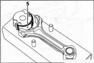
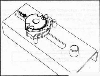
5. Push the liner holder in the direction shown by the arrow in the figure until the liner holder is fully seated in the connecting rod body.
6. Remove the holder of a rod of a rod and carry out the same operations with other rods.
Installing the liner in the cap of the crank head of the connecting rod
1. Install the connecting rod cap onto the tabs (6) base, and then place the insert on the holder (7).
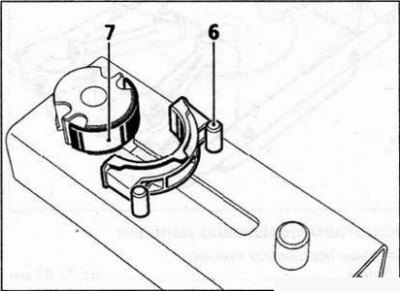
2. Push the bushing holder in the direction shown by the arrow in the figure until the bushing holder is fully seated in the connecting rod cap.
3. Visually check:
- condition of connecting rods (they can be twisted or bent);
- secure seating of the bearing caps on the connecting rods (if necessary, use an emery board to remove burrs to ensure proper seating of the caps).
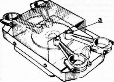
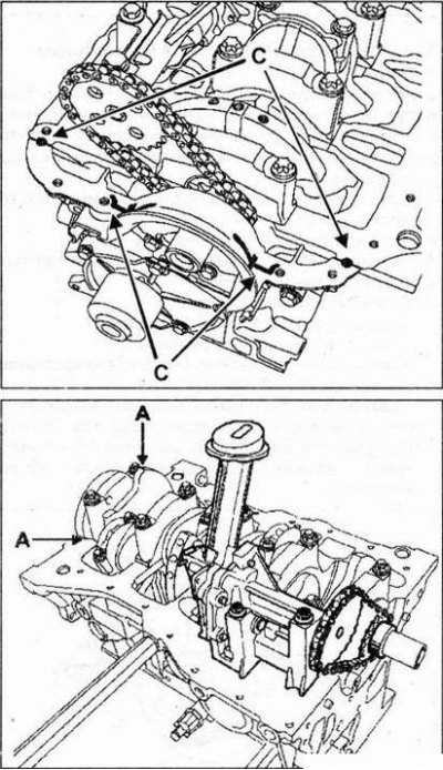
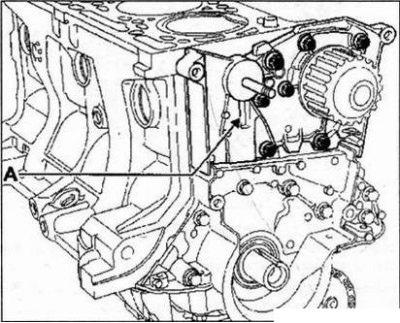
4. Lay the upper ends of the connecting rods on the heating plate. Use a 1500W hotplate. Ensure that the surface of the upper head of the connecting rod is firmly attached to the plate.
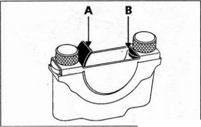
To control the heating temperature of the connecting rods, put on the top head of each connecting rod in the area (A) a small piece of tin solder with a melting point of approximately 250°C.
Heat the top ends of the connecting rods until the solder melts.
Piston pin preparation
Piston pin dimensions:
- Length - 61.7-62 mm
- Outside diameter - 19.986 - 19.991 mm
- Inner diameter - 11.6 mm
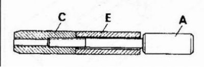
Make sure the piston pins fit freely into the corresponding new pistons. Use centering tool C13 and locating rod A13 or tool Mot.574-24.
Install piston pin (E) on the mounting rod (A), screw in the centering tool (WITH) until it stops and then unscrew it 1/4 turn.
Connecting rod assembly with piston
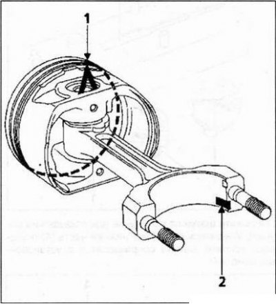
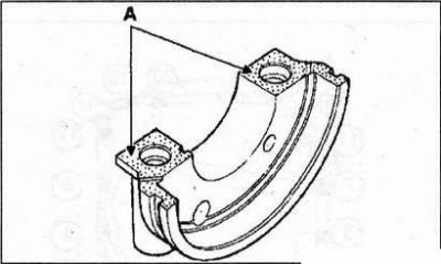
Piston bottoms are marked "A", indicating direction towards the flywheel.
The location of the pistons relative to the connecting rods
Install the piston so that the mark "A" (1) on its bottom was at the top.
Install the connecting rod so that the locking lug (2) connecting rod bearing was at the bottom.
When assembling the piston with the connecting rod, follow the instructions below:
- Install the ring B10 on the stand and place the piston on this ring, securing it with your finger.
- Make sure the piston pin hole is aligned with the hole in the B10 ring.
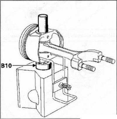
- Lubricate the centering tool and piston pin with engine oil.
- Insert the piston pin so that it freely enters the piston and, if necessary, re-center the piston.
Attention! Subsequent operations must be carried out as quickly as possible to avoid cooling the connecting rod.
When the solder temperature reaches the melting point (solder will turn into a drop):
- wipe off a drop of solder;
- insert the centering device into the piston;
- insert the connecting rod into the piston;
- insert the piston pin as far as the stop of the centering device into the support as quickly as possible.
Make sure the piston pin stays inside the piston in all positions of the connecting rod in the piston.
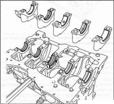
Inserts of radical bearings of a cranked shaft
The engine is equipped with liners that do not have protection against incorrect installation.
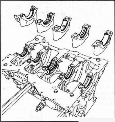
Installation sequence:
- Install grooved shells in all bearing seats in the crankcase.
- Install the grooved shells on the main bearing caps 2 and 4, and the non-grooved shells on the main bearing caps 1, 3 and 5.
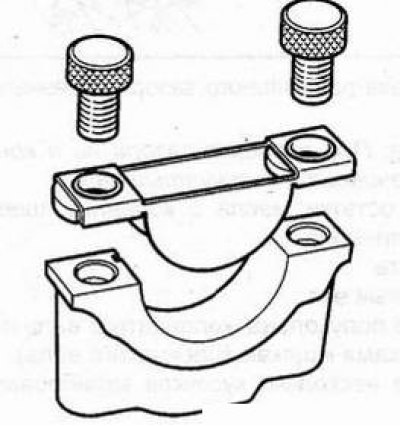
1. Installation of liners in the cylinder block. Install tool Mot. 1493-01 to the main bearing seat on the crankcase.
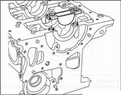
Insert insert into Mot. 1493-01, then press on the point (A), so that the insert touches Mot. 1493-01 dot (IN).
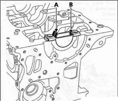
2. Installing liners in the main bearing caps.
Install tool Mot. 1493-01 on the main bearing cap.
Insert insert into Mot. 1493-01, then press on the point (A), so that the insert touches Mot. 1493-01 dot (IN).
Install:
- install bearing shells without grooves in covers 1-3-5;
- install bearing shells with grooves in the bearings of the cylinder block and in the bearing caps 2-4;
- install the crankshaft side adjusting semi-rings into the main bearing seat 3 (grooves towards the crankshaft).
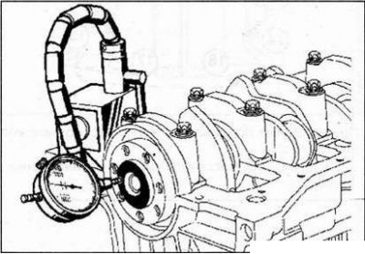
3. Checking the radial clearance of the main bearings.
Attention! When checking the clearance, never turn the crankshaft.
Remove oil residues from the main journals and bearings of the cylinder block.
Install:
- crankshaft;
- thrust half rings of the crankshaft on the 3rd bearing (grooves to the cheeks of the crankshaft). Cut several pieces of calibrated wire.
Lay the wire along the axis of the main journals of the crankshaft (outside the area of the holes for greasing the bearings).
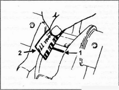
1 - calibrated wire, 2 - scale.
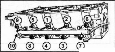
Install the crankshaft bearing caps (they are numbered from 1 to 5), by installing the cover on the flywheel side. Tighten the mounting bolts in the order shown in the figure with a torque of 25 Nm and tighten them by 47°±5°.
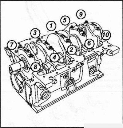
The order of tightening the bolts of the crankshaft main bearing caps.
Remove the crankshaft main bearing caps and crankshaft.
Using the scale printed on the package, by flattening the calibrated wire, determine the gap between the liners and the main journals
Gap - 0.027-0.054 mm
Clean the crankshaft and bearing caps from the remnants of the calibrated wire. 4. Reinstall the crankshaft bearing caps and tighten the mounting bolts.
Note. Remember to apply a thin layer of RHODORSEAL 5661 to the N9 bearing 1 in the area (A).
5. Check the axial clearance of the crankshaft, which should be within 0.045 - 0.252 mm in the absence of wear on the adjusting half rings and within 0.045 - 0.852 if they are worn.
Make sure the crankshaft turns freely.
Installation of piston rings
Each piston has three rings.
Ring thickness:
- Top compression ring - 1.2mm
- Lower compression ring - 1.5 mm
- Oil scraper ring - 2.5 mm
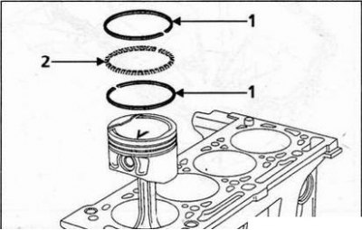
The oil scraper ring consists of three parts: two steel rings (1), dual function ring expander (2).
Piston rings installed at the factory must move freely in their piston grooves.
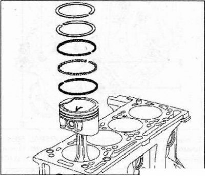
Install piston rings correctly: mark "TOR" should be at the top. Orientation of the piston rings on the piston: Position the piston rings as shown in the figure below.
Installing piston assemblies in cylinders
1. Lubricate the pistons.
2. Insert the piston assembly with the connecting rod into the cylinder block using a compression clamp (for example: FACOM 750 TV), providing the right direction (label "A" must face the flywheel).
3. Install the connecting rods on the lubricated crankshaft cranks.
4. Put on covers of the lower heads of rods.
5. Tighten new connecting rod cap nuts to 43 Nm.
6. Reinstall:
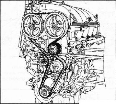
- oil pump drive sprocket;
- oil pump drive chain;
- oil pump, tighten its mounting bolts with a torque of 22 - 27 Nm;
- crankshaft seal cover with Loctite 518 sealant (IN) The sealant should be 0.6 - 1mm wide and the sealant should be applied as shown in the figure below.
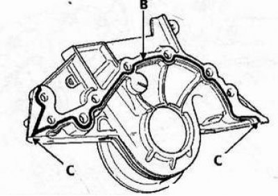
Then tighten the crankshaft front oil seal retainer bolts to 11 Nm in the recommended sequence.
7. Apply a drop of RHODORSEAL 5661 at the points (A) (on both sides of bearing No. 1) and on the holder of the front crankshaft oil seal (WITH).
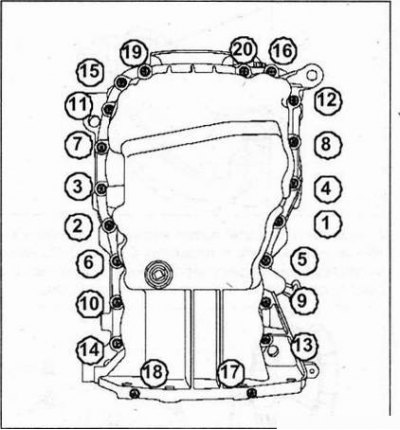
8. Install the oil separator and pan with a new gasket. Tighten the pan bolts in the order shown in the figure to 8 Nm and then finally tighten them to 14 Nm.
When installing the engine tray, make sure that:
- ledges (1) oil separators are installed in grooves (2);
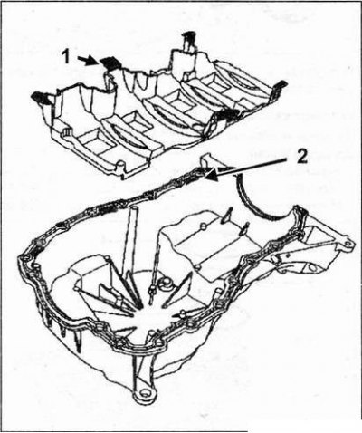
- The cylinder block and engine sump are aligned on the flywheel side to prevent damage to the clutch housing when connecting the engine to the transmission.
9. Install the oil level sensor.
- Tightening torque - 20 Nm
10. Install the knock sensor.
- Tightening torque - 20 Nm
11. Install the oil pressure switch.
- Tightening torque - 32 Nm
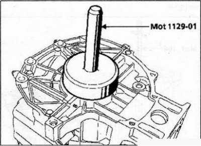
Installation of crankshaft seals
1. Use tool Mot 1129-01 to install oil seals on the flywheel side.
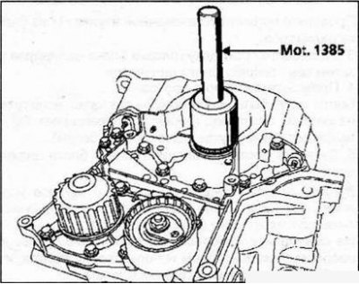
2. Use tool Mot 1385 to install oil seals on the timing side.
3. Reinstall:
- flywheel by tightening the new bolts of its fastening with a torque of 55 Nm (in star order);
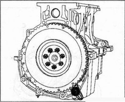
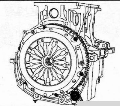
- clutch basket.
Center the driven disc with a mandrel (Emb. 1581).
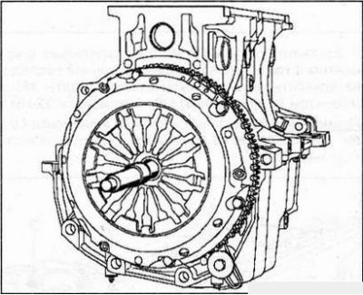
Tighten the clutch cover mounting bolts to 18 Nm and remove the flywheel retainer.
4. Replace the water pump, sealing its seating surface with Loctite 518. Strip Width (WITH) the sealant should be 0.6-1mm, and the sealant should be applied as shown in the figure below.
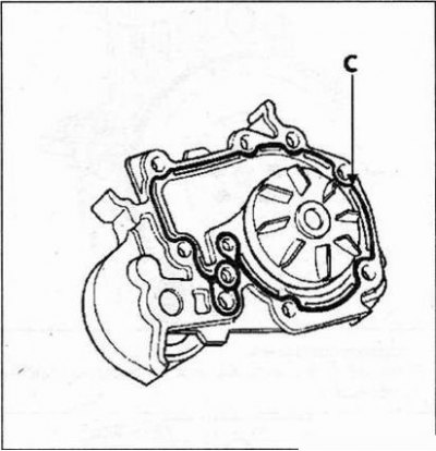
5. Tighten the Mb and M8 bolts first with a torque of 8 Nm and then, in the recommended sequence, finally tighten the Mb bolts with a torque of 11 Nm, and the M8 bolts with a torque of 22 Nm.
Note. Apply 1-2 drops of Loctite FRENETANCH to bolts 1 and 4 of the water pump mounting.
6. Reinstall:
- timing belt tensioner pulley by correctly positioning the lug of the pulley in the groove (A);
- oil level sensor.
Installing the cylinder head
1. Install pistons at mid stroke.
2. Install tool Mot. 104 per cylinder block.
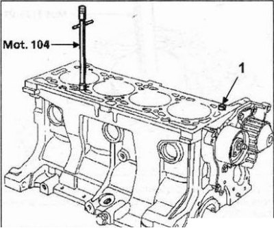
Check the presence of the mounting sleeve (1) on the cylinder block.
3. Install the cylinder head gasket and then the cylinder head itself.
4. Check up a condition of bolts.
Bolts can be reused if the length of the bolt shaft under the head does not exceed 117.7 mm (otherwise, replace all bolts).
5. Tighten the cylinder head bolts.
Attention! To properly tighten the bolts, use a syringe to remove the oil remaining in the mounting holes of the cylinder head.
Do not lubricate new bolts with engine oil. Conversely, when reusing bolts, they must be lubricated with engine oil.
Check that all bolts are tightened to 20 Nm, then turn all bolts 240°±6°in the same order.
Note. After this procedure, re-tightening of the cylinder head bolts is not required.
6. Reinstall the fuel distribution rail and tighten its fastening bolts to a torque of 20 Nm.
Note.
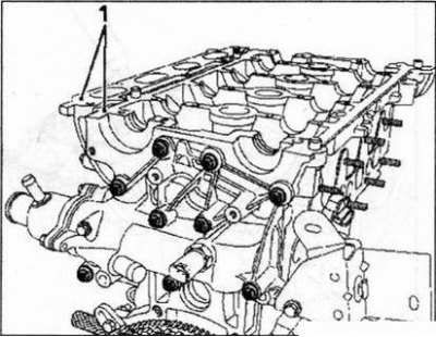
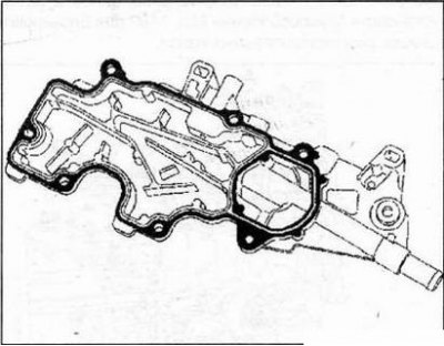
- Check the alignment of the lower inlet distributor with the cylinder head (on the distribution side).
- Check top surface alignment (1) lower intake distributor with cylinder head.
7. Reinstall the removable part of the cooling jacket with a new seal and tighten the mounting bolts with a torque of 10 Nm.
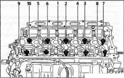
All bolts are tightened to 20 Nm in the order shown in the figure.
8. Reinstall:
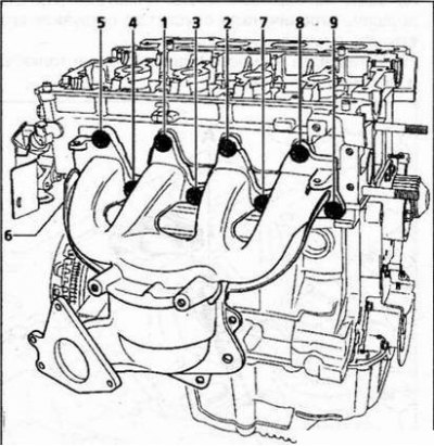
- exhaust manifold with a new gasket, tightening its fastening nuts with a torque of 18 Nm in the recommended sequence;
- the upper heat shield of the exhaust gases by tightening the bolts of its fastening with a torque of 10 Nm;
- oxygen sensor by tightening it with a torque of 45 Nm;
Note. Check that the exhaust heat shield is properly installed between the oxygen sensor and the exhaust manifold (this prevents heat stress that could destroy the oxygen sensor connector).
- strut between the exhaust manifold and the cylinder block;
- spacer (A).
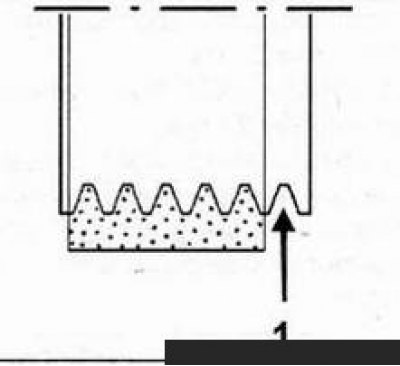
9. Over time, the working fluid from the hydraulic tappets flows out and needs to be replenished. To check if these tappets require fluid replenishment, press the top of the tappet with your thumb (A). If the restrictor piston drops, immerse it in a container of diesel fuel.
10. Reinstall the hydraulic tappets and rocker arms.
11. Lubricate the camshaft bearings.
Note. Do not allow oil to come into contact with the cylinder head cover gasket surface.
12. Install the camshafts correctly (see subsection "Camshafts" section "Engine disassembly"). Install the camshaft grooves as shown in the figure below.
Note. Gasket surfaces must be clean, dry and free of grease (especially avoid touching them with your fingers, so as not to leave traces of fat).
13. Using a roller, apply Loctite 518 sealant to the surface of the cylinder head cover on the side of its gasket until it acquires a reddish color.
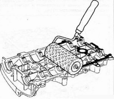
Table. Tightening order for cylinder head cover bolts
| Stage | Bolt tightening sequence | Bolt loosening sequence | Torque (Nm) |
| №1 | 22-23-20-13 | - | 8 |
| №2 | 1 to 12; from 14 to 19; from 21 to 24 | - | 12 |
| №3 | - | 22-23-20-13 | - |
| №4 | 22-23-20-13 | - | 12 |
14. Reinstall the cylinder head cover and tighten its fastening bolts to the recommended torque.
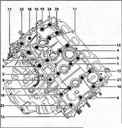
Tightening order for the cylinder head cover bolts.
15. Using a roller, apply Loctite 518 to the gasket side of the oil sump until it turns reddish.
Note. Gasket surfaces must be clean, dry and free of grease (especially avoid touching them with your fingers, so as not to leave traces of fat).
16. Replace:
- oil sump by tightening the mounting bolts with a torque of 13 Nm in the recommended sequence (self-tapping bolts should be tightened with a torque wrench);
- lifting eye (A).
17. Replace:
- ignition coils by tightening the mounting bolts with a torque of 13 Nm;
- intake manifold (with new seals), by tightening the bolts of its fastening with a torque of 9 Nm in the recommended sequence;
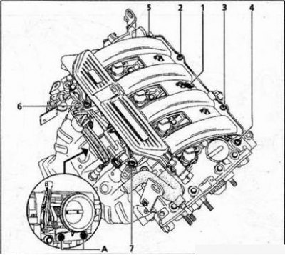
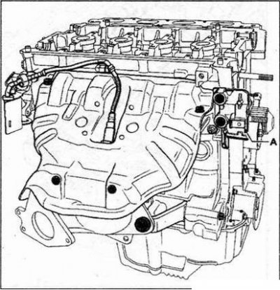
- throttle body by tightening its fastening bolts (A) with a moment of 13 Nm;
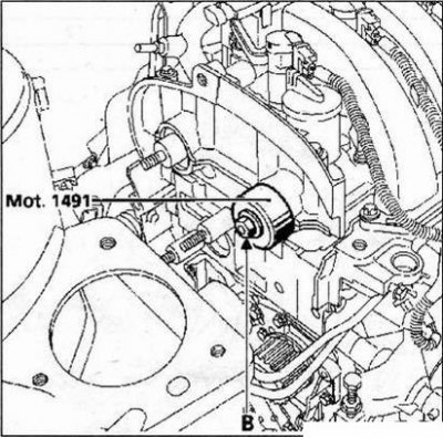
- air filter by tightening its mounting bolts to 9 Nm, the camshaft seals using tool Mot. 1491 (use old nuts (IN)).
Setting the valve timing
Attention! It is necessary to degrease the crankshaft end journal, the seating surfaces of the timing gear pulleys and the crankshaft to prevent slippage between the timing mechanism and the crankshaft, which can cause engine damage.
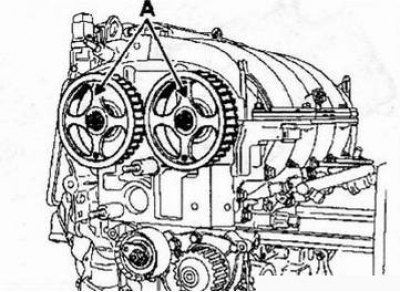
1. Reinstall the camshaft pulleys, after tightening the new nuts (old nuts must be replaced with new ones, without nuts, the axial play between the nut and the pulley must be within 0.5-1 mm).
2. Install the camshaft grooves as shown in the figure below.
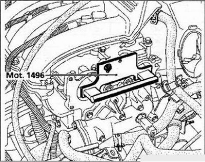
3. Install tool Mot. 1496 by attaching it to the ends of the camshafts.
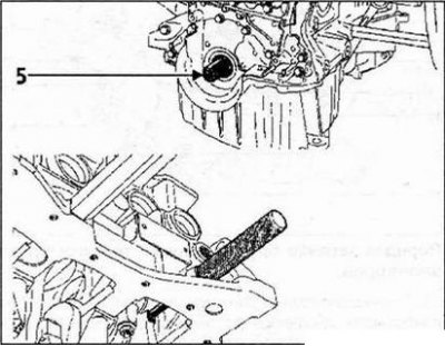
4. Make sure that the crankshaft rests against the TDC position lock (while the groove (5) on the crankshaft is in the highest position).
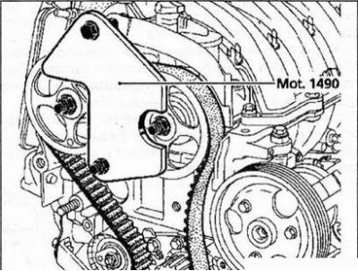
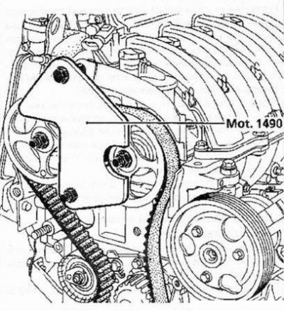
5. Install the camshaft pulleys so that the logo "Renault" on their spokes was oriented vertically upwards. Fit the timing belt onto the camshaft pulleys and then install tool Mot. 1490 to lock the camshaft pulleys.
6. Reinstall:
- timing belt drive;
- pulley by tightening the mounting bolt with a torque of 45 Nm.
Note. The crankshaft pulley bolt for driving auxiliary equipment can be reused if its length under the head does not exceed 49.1 mm; otherwise, replace it with a new one.
7. Reinstall the crankshaft pulley for driving auxiliary equipment, after tightening its fastening bolt (without tightening the bolt, there should be a play of 2-Zmm between the bolt head and the pulley).
Note. Do not lubricate the new bolt. However, if an old bolt is used, it must be lubricated with engine oil.
Belt tension
1. Make sure that there is still 0.5-1 mm play between the nuts and the camshaft pulleys.
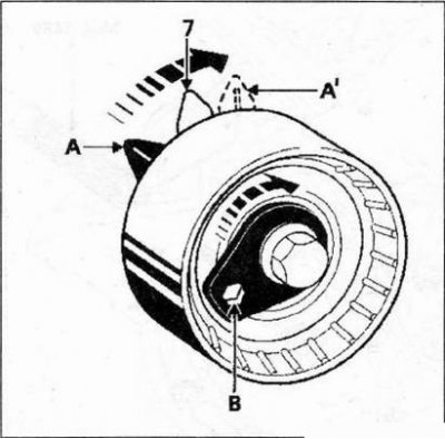
2. Move the moving mark (A1) tension roller by 7-8 mm relative to the fixed mark (7), using a 6 mm hex socket wrench (IN).
Note. Dot (A) corresponds to the movable mark in the free position.
3. Pre-tighten the tension roller nut with a torque of 7 Nm.
4. Remove tool Mot. 1490 to lock the camshaft pulleys.
5. Rotate the exhaust camshaft pulley on the timing side six times using tool Mot. 799-01.
6. Loosen the idler nut no more than one turn while holding the roller with a 6mm hex socket wrench.
7. Align the moving mark (A') with fixed mark (7) and tighten the roller nut to 27 Nm.
8. Install tool Mot. 1490 to lock the camshaft pulleys.
10. Tighten the accessory crankshaft pulley bolt to 20 Nm and then screw it in at an angle of 135°±15° (in this case, the crankshaft must rest against the TDC position lock).
11. Tighten the intake camshaft pulley nut to 30 Nm and then screw it in at an angle of 84°.
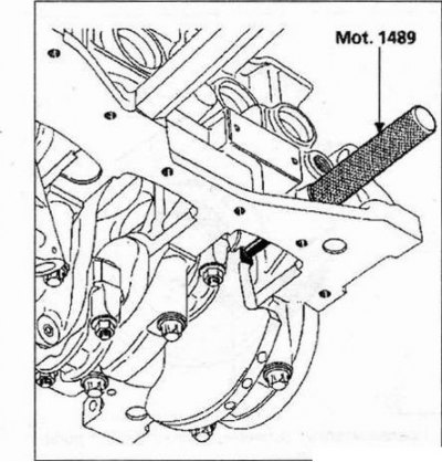
12. Remove tool Mot. 1496 for correct alignment of the camshafts, tool Mot. 1490 for locking the camshaft pulleys and TDC position lock Mot. 1489.
Belt tension check
1. Turn the crankshaft clockwise (from the gas distribution mechanism) two turns; until the end of the second turn, screw in lock Mot. 1489 into the cylinder block and slowly, without jerking, tighten the crankshaft in the same direction until it rests on the TDC position lock.
2. Remove the TDC position lock.
3. Make sure that the alignment marks of the tension roller are aligned; otherwise, repeat the belt tensioning operation.
4. Loosen the idler nut no more than one turn while holding the idler with a 6mm hex socket wrench.
5. Align the moving mark with the fixed mark and tighten the roller fastening nut to a torque of 27 Nm.
Checking the correct installation of the valve timing
1. Before checking the correct installation of the valve timing, make sure that the tension roller marks are in the correct position.
2. Screw in the TDC positioner Mot. 1489 into the cylinder block, position and hold the crankshaft in a position where it rests against the position lock. 3. Install (without making any effort) tool Mot. 1496 for the correct installation of camshafts (camshaft grooves must be horizontal). If the indicated device does not engage, this means that the valve timing must be reinstalled and the belt tension adjusted again.
9. Check that the crankshaft rests against the TDC positioner Mot. 1489.
4. Reinstall:
- stopper of the hole of the TDC position lock;
- the top cover of the timing mechanism, tightening the bolts of its fastening with a torque of 41 Nm;
- middle cover of the timing mechanism.

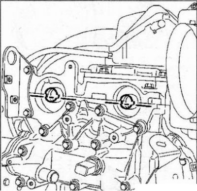
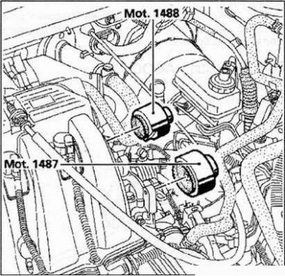
5. Install new plugs:
- intake camshaft (Mot. 1487);
- exhaust camshaft (Mot. 1488).
Final operations
1. Replace:
- water pipe with new seal;
- universal mounting bracket (before tightening its fastening bolts, make sure that it touches the oil pan in the position (A) and then tighten the mounting bolts (see table "Universal Mounting Bracket Torques").
Table. Universal Mounting Bracket Torques
| bolts | Tightening torques |
| 1 | 53 Nm |
| 2 | 21 Nm |
| 3 | 110 Nm |
2. Reinstall:
- air conditioning compressor by tightening the mounting bolts with a torque of 21 Nm;
- alternator by tightening the mounting bolts with a torque of 21 Nm;
- power steering pump by tightening the mounting bolts with a torque of 21 Nm;
- accessory drive belt.
3. Attachment drive belt (models with air conditioning).
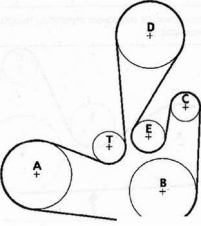
A - Crankshaft pulley, B - A/C compressor pulley, C - Alternator pulley, D - Power steering pump pulley, E - Bypass pulley, T - Idler pulley.
To put on the belt, turn the wrench to the left.
Lock the idler pulley using a 6mm hex socket wrench (1).
Note. Check that the inner stream (1) the pulleys remain free when the belt is installed.
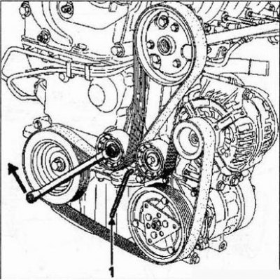
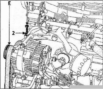
4. Attachment drive belt (models without air conditioning).
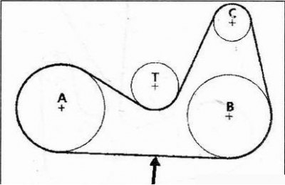
A - Crankshaft pulley, B - Power steering pump pulley, C - Alternator pulley, T - Idler pulley, Belt tension test point.
The drive belt is tensioned with a bolt (1) (at the same time, it is necessary to loosen the two bolts of the tension rollers) followed by tightening the nut (2).
Tighten the auto tensioner bolts.
Note. The attachment drive belt has five wedges, and the alternator pulley and the power steering pump pulley are 6-strand; therefore, when installing a greeting belt, it is imperative to leave the outer pulley stream free (E).
5. To properly install the accessory belt on the pulleys, turn the engine crankshaft two turns.