
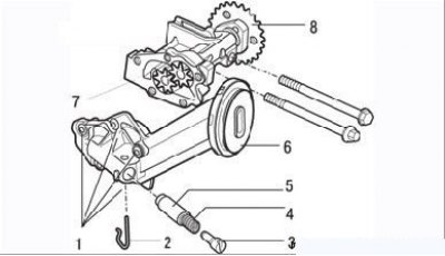
Figure 3.90. Oil pump details: 1 - bolts; 2 - hairpin; 3 - adjusting screw of the pressure reducing valve; 4 - spring; 5 - plunger of the pressure reducing valve; 6 - oil receiver; 7 - pump casing; 8 - drive sprocket
Operating procedure:
- remove the oil pump as described earlier;
- unscrew the mounting bolts, remove the cover and oil receiver;
- remove the pin, adjusting screw, spring and plunger of the pressure reducing valve;
- carefully inspect the pump gears and relief valve parts. External damage, increased wear are not allowed;
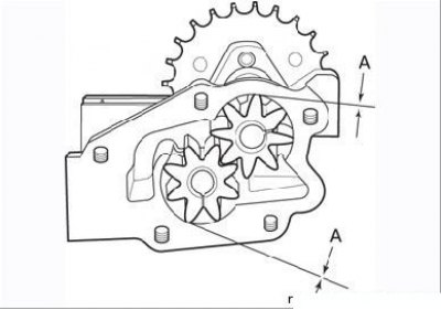
Figure 3.91. Gap measurement (A) between gears and oil pump housing
- measure the clearance between pump housing and gears (Figure 3.91), it should be in the range of 0.110–0.249 mm;
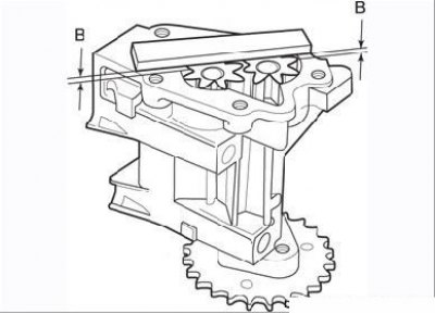
Figure 3.92. Axial clearance measurement (IN) oil pump gear
- measure the axial clearance of the gears (Figure 3.92). The gap should not be more than 0.020–0.086 mm. If the clearances are out of range, replace the oil pump;
- check the flatness of the cover adjacent to the pump housing.
If the condition of the pump parts is satisfactory, assemble the pump in the reverse order of removal, fill the housing with clean engine oil and install, tightening the bolts to the required torque.
Checking the oil pressure in the lubrication system
Disconnect wires from the gauge of a control lamp of an emergency drop in pressure of oil, turn out the gauge and screw instead of it the union of a hose of a control manometer.
Start the engine and warm it up to an oil temperature of 80°C. Measure the oil pressure at idle and at a crankshaft speed of 3000 min–1, which should be respectively 1 and 3 bar.
Disconnect the control pressure gauge, install the sensor and connect the wires to it.