
- place the cylinder block on a clean horizontal surface with the crankcase up;
- Wipe dry with a lint-free cloth the backs of the earbuds and their beds in the block and covers;
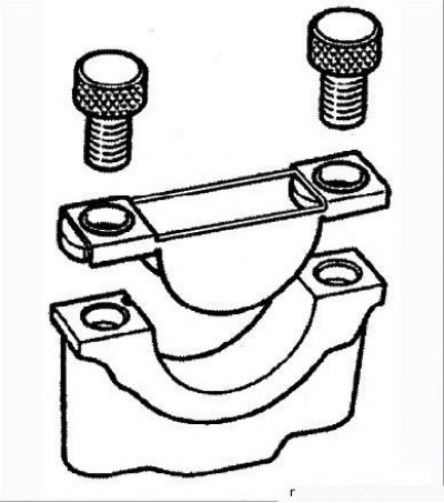
Figure 3.70. Renault tool Mot. 1493-01 for pressing bed liners
- place the liners in their respective beds using the Renault tool Mot. 1493-01 (Figure 3.70);
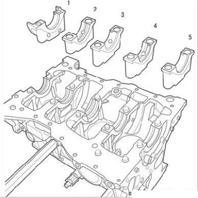
Figure 3.71. Installing the crankshaft main bearing shells
- Install grooved liners in the cylinder block bed. In the covers of supports 1, 3, 5 (Figure 3.71) install liners without grooves, and in covers 2 and 4 - with grooves;
- install thrust half rings on both sides of the 3rd support of the cylinder block. The lubrication grooves must face outward;
- check the clearances in the crankshaft bearings before final installation using a special Plastigage kit. The set is a plastic calibrated round bar. If a piece of bar is clamped between two parts, then by its deformation, using the attached scale, you can determine the gap between these parts;
- Carefully place the crankshaft into the cylinder block. Do not use grease on either the shaft or the bushings;
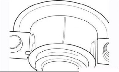
Figure 3.72. A piece of Plastigage plastic bar laid on the crankshaft main journal
- cut five pieces of plastic rod and lay them on each main shaft, as shown in Figure 3.72;
- carefully, without moving the bars, place the corresponding covers with the liners installed in them on the supports;
- starting from the 3rd support, tighten the cover bolts in the prescribed order to the specified torque; do not rotate the crankshaft while tightening the covers;
- unscrew the bolts securing the covers and carefully remove them without moving the flattened bar from the surface of the shaft neck;
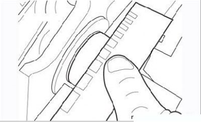
Figure 3.73. Determining the clearance in the bearing according to the Plastigage scale
- use the scale supplied with the kit to determine the clearances in each bearing (Figure 3.73). Compare the results obtained with those given in tab. 3.3;
- if the gaps are larger than allowed, the bearings may not be the correct size (or too worn, if the measurement was set to the previous). Before deciding on a crankshaft, make sure that no oil or dirt has entered the gap where the measuring rod was installed. If the flattened bar is wider at one end than at the other, it is likely that the neck has tapered wear. Consult with an engine rebuilder whether to rebuild worn parts or replace them with new ones;
- at the end of the operation, scrape off with a soft scraper all the remnants of the bar from the surfaces of the bearings and the shaft, being careful not to damage the bearings;
- carefully remove the crankshaft from the cylinder block;
- Wipe the bearing shells and crankshaft journals again with a rag. Make sure that there are no dirt, dust, Plastigage residues in the lubrication holes and on the surfaces of the crankshaft, as this dirt will be in the bearings after the first start of the engine;
- lightly grease the thrust half rings on the side of the 3rd support and install them outward with the lubrication grooves;
- lubricate the bearing shells with clean engine oil, then carefully install the crankshaft on the bearing journals;
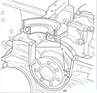
Figure 3.74. Clean contact surfaces before applying sealant (A) covers of the 1st support
- make sure the bushings are properly installed in the bearing caps, lubricate them with clean engine oil and install on the block in the required order with the correct orientation, while applying a thin layer of PHODORSEAL 5661 sealant to the entire contact surface of the 1st bearing cap (Figure 3.74 and 3.75);
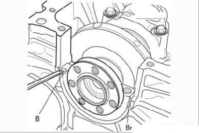
Figure 3.75. Applying sealant to the underside (IN) cylinder block
- install the bolts on the support covers and tighten them diagonally from the middle outwards in a certain order with the set torque;
- check the rotation of the crankshaft - it should be easy, without jamming. If force is required to rotate, find out the cause before proceeding with further assembly;
- check the axial clearance of the crankshaft as described above;
- install the crankshaft oil seal on the flywheel side;
- Install the lower rear timing belt cover.