



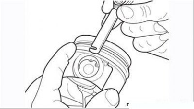
Figure 3.55. Removing piston rings using a feeler gauge
Clean the pistons and connecting rods from dirt and carbon deposits. Using two or three flat feeler gauges, remove the rings from the pistons upwards (towards the piston bottom) (Figure 3.55). Clean the piston crown from carbon deposits using an aluminum scraper. Do not use sandpaper for this purpose, as the abrasive grains penetrate the piston aluminum and subsequently cause scratches. Remove carbon deposits from the piston grooves using a suitable piece of piston ring, being careful not to scratch the groove surface.
Wash the pistons from the removed carbon deposits. Make sure that the holes in the oil scraper grooves are not clogged with dirt.
Inspect the rubbing surfaces of the pistons. Wear in the form of vertical "bald spots" on the pressure-bearing surface of the piston skirt and a small gap in the fit of the upper compression ring in the groove are considered acceptable. Scoring and scratches on the piston skirt may indicate that the engine was overheated for some reason: poor cooling, lubrication, too high a combustion temperature. Traces of burning on the skirt are a sign of gas leakage from the combustion chamber, possibly caused by wear of the cylinder walls or piston rings. Traces of burning or chipping on the piston crown are usually signs of engine operation with detonation caused by early ignition or the use of low-quality gasoline. In some cases, the piston head may be melted for the same reason. An over-lean mixture due to air leakage at the intake can also cause piston overheating.
All causes of the listed damage must be eliminated before the engine is put into operation, otherwise similar damage to the piston group will occur again.
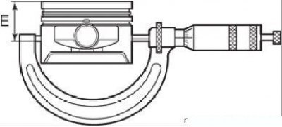
Figure 3.56. Measuring the piston diameter using a micrometer: E=(42±0.01) mm
Using a micrometer, measure the diameters of all four pistons at a distance of (42±0.01) mm from the piston bottom (Figure 3.56) perpendicular to the piston pin axis. Compare the measurement results with those shown in Table 3.4.
Table 3.4. Dependence of piston diameter on cylinder diameter
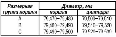
If the piston diameter is out of tolerance, replace the entire piston set. Keep in mind that the cylinder block may have been bored during a previous overhaul, and oversized pistons may have been installed. Record the measurements and use them to check the clearances later when the cylinder diameters are measured.
Measure the gaps between the piston rings and the piston grooves by installing the rings in the grooves and using a set of flat feeler gauges, take the appropriate measurements in three or four places in each groove. The measured dimensions should not exceed 0.1 mm, otherwise the pistons will need to be replaced.
Carefully inspect the connecting rods, pins and caps for wear, cracks and other surface damage. Visually inspect the following:
- condition of connecting rods (they may be twisted or bent);
- tightness of bearing caps fit on connecting rods (if necessary, use a sanding block to remove burrs to ensure proper seating of the caps).
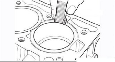
Figure 3.57. Measuring the gap in the piston ring lock
Before putting the rings on the pistons, install them one by one into your cylinder and check the gap in the ring lock. Use the piston to push the ring into the cylinder so that the plane of the ring is parallel to the upper plane of the block (Figure 3.57). Compare the measurement results with those shown in Table 3.3.