
Do the following:
- install the cylinder block on the workbench crankcase up;
- install the piston of the first cylinder (flywheel side) to the NMT position;
- paint a mark on the connecting rod and its cap (in the absence of numbering) for proper installation during assembly;
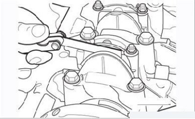
Figure 3.53. Measuring the backlash of the bottom cap of the connecting rod
- use a feeler gauge to check the bottom end clearance of the connecting rod (Figure 3.53) and compare the result with the dimensions given in Table. 3.3;
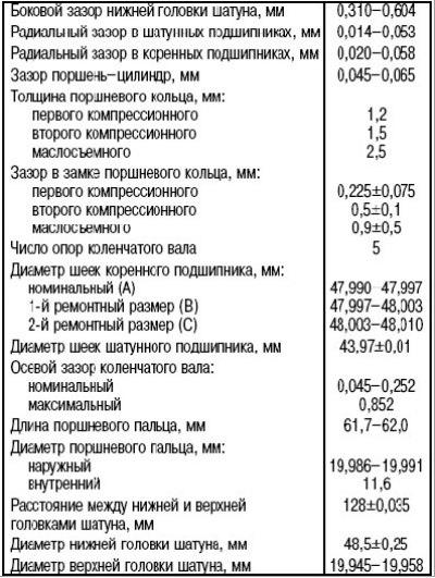
Table 3.3. Technical data of the crankshaft and parts of the connecting rod and piston group
- unscrew the nuts securing the lower connecting rod cover and remove the cover together with the insert. Attach the insert with adhesive tape to the storage lid. Reusing the inserts is not recommended, but if they are to be used again, they should be reinstalled;
- put plastic tubes on the connecting rod cap bolts or wrap them with adhesive tape to prevent damage to the cylinder surface when removing the piston from the block;
- inspect the top of the cylinder mirror. If there is a significant ledge there, it must be removed, since the piston and its rings can be damaged during removal;
- paint numbers on the bottoms of all pistons;
- Carefully remove the piston through the top of the cylinder block by pressing down on the piston head with a suitable wooden rod. Once the piston and connecting rod have been removed, remove the upper bearing shell and tape it to the connecting rod for storage;
- turning the crankshaft half a turn, remove the pistons and connecting rods of the remaining cylinders in the same way. Before removing parts, mark them (or make sure you have it);
Attention! The piston pins are pressed tightly into the upper ends of the connecting rods and have a floating fit in the piston bosses. Retaining rings are not used.
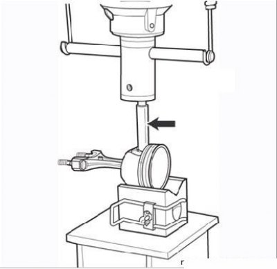
Figure 3.54. Removing the piston pin from the piston using a mandrel (arrow)
- install the piston in the V-shaped stand so that the piston pin aligns with the hole to remove it (Figure 3.54);
- using a piston pin extractor, remove it from the piston using a press.