



Assembly
Assembly order:
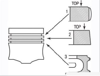
Figure 3.58. Piston ring profiles
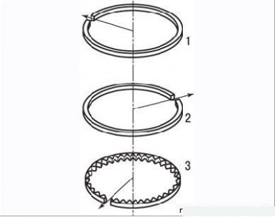
Figure 3.59. Location of piston ring locks at an angle of 120° relative to each other
- install the rings on the pistons - put them on through the piston crown, starting with the oil scraper ring and using the same flat feeler gauges that were used to remove the rings. The piston ring profiles are shown in Figure 3.58. The compression rings are installed with the "TOP" marking facing up. They are very fragile, so be careful when installing them. Spread the piston ring locks at an angle of 120° relative to each other (Figure 3.59);
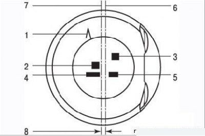
Figure 3.60. Piston marking: 1 – direction of piston installation with the "L" mark towards the flywheel; 2, 4, 5 – supplier marking; 3 – piston size group (A–B–C); 6 – axis of symmetry of the piston; 7 – piston pin bore axis; 8 – the offset of the axis (7) of the hole for the piston pin relative to the plane of symmetry (6) of the piston is 0.9 mm
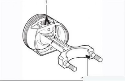
Figure 3.61. Position of the connecting rod relative to the piston: the "L" mark (1) on the piston bottom should be at the top, and the locking protrusion of the bearing shell (2) of the lower connecting rod head should be at the bottom
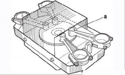
Figure 3.62. Heating the upper heads of the connecting rods on an electric stove: a - a piece of tin solder
[Original article is on the portal: renaultbook.ru]
- assemble the piston with the connecting rod. Mark "L" on the piston bottom (Figure 3.60) should be directed towards the flywheel and the locking lug of the connecting rod small-end bearing shell should be as shown in Figure 3.61. Place the connecting rod small-ends on a 1500 W hot plate as shown in Figure 3.62. To control the heating temperature of the connecting rods, place a small piece of tin solder with a melting point of approximately 250°C on the small-end of each connecting rod in area a;
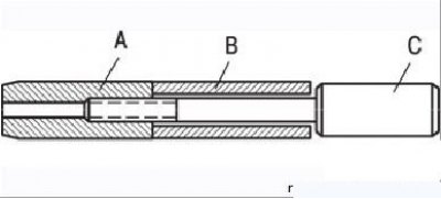
Figure 3.63. Installing the piston pin (B) on the mounting rod (C) and connecting it to the centering device (A)
- prepare the piston pins. Make sure they fit freely into their respective pistons. Install the piston pin on the installation rod, screw the centering device in until it stops, and then back it out 1/4 turn (Figure 3.63);
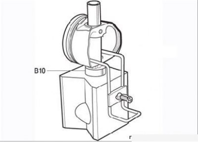
Figure 3.64. Installing the piston on the assembly fixture with the connecting rod: B10 – limiter sleeve
- install the piston on the support, orienting it as shown in Figure 3.61. Place a bushing between the piston and the support to limit the movement of the centering device when pressing in the piston pin (Figure 3.64);
- lubricate the centering device and piston pin with engine oil;
Caution! The following operations must be performed as quickly as possible to avoid cooling the connecting rod.
- when the solder temperature reaches the melting point (the solder will turn into a drop), wipe off a drop of solder;
- insert the connecting rod into the piston;
- insert the piston pin as quickly as possible until the centering device stops in the support;
- remove the centering device from the pin;
- make sure that the piston pin does not extend beyond the piston bosses in any position of the connecting rod.