



2. Rotate the crankshaft so that connecting rod #1 is at BDC. If there is no number on the connecting rod and cap, mark them with a punch (see illustration) according to the number of cylinders in which they are installed.
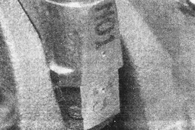
12.2. The connecting rod caps are marked with a punch.
3. Before removing the covers, check the lateral clearance between the covers and the crankshaft counterweights (see illustration).
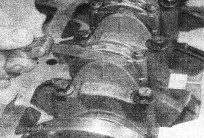
12.3. Check the lateral play of the connecting rod cap.
4. Unscrew and remove the nuts (c- and E-series engines) or bolts (d- and F-series engines) connecting rod bearing caps. Remove the cover together with the insert.
5. If you only need to inspect the bearings, push the connecting rod off the crankshaft journal and remove the upper bearing. Store the liners and lid together.
C- and E-series engines
6. Remove the cylinder liner clamps and remove the liners together with the pistons and connecting rods through the top of the cylinder block. Mark the sleeves with adhesive tape so that they can be installed in their original place.
7. Remove the piston from the base of the sleeve.
D- and F-series engines
8. Push the piston with the connecting rod out of the cylinder bore. Please note that if there is a wear ridge at the top of the cylinder, there is a risk of piston damage.