



Contents: Cleaning 🠛 Inspection and maintenance 🠛
1. Complete cleaning of head components
cylinder block and valves followed by a detailed inspection will allow you to determine what procedures need to be performed during engine overhaul.
Cleaning
2. Clean all traces of the old gasket from the cylinder head.
3. Clean any carbon deposits from the combustion chambers and bores, then thoroughly wash the cylinder head with kerosene or a suitable solvent.
4. Scrape off most of the carbon deposits from the valves, then use a wire brush to remove any remaining carbon deposits from the valve heads and stems.
Inspection and maintenance
Note: Complete all inspection procedures before concluding that it is necessary to take the tire to a repair shop for regrinding. Make a list of all components that require processing.
Cylinder head
5. Carefully inspect the head for cracks and other damage, as well as coolant leaks. If cracks are found, replace the head.
6. Use a straight edge and feeler gauge to ensure that the cylinder head surface is not deformed (see illustration).
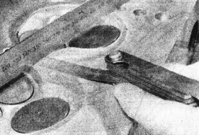
8.6. Check the cylinder head surface for deformation.
On the C-series engine, it is possible to regrind the head surface. The manufacturer does not recommend grinding the head surface on other engines, and the only solution is to replace the cylinder head.
7. Inspect the valve seats in each combustion chamber. If they are heavily pitted, cracked or burnt, have them re-sharpened by a specialist. If the pitting corrosion is minor, it can be removed by grinding the valve head and seat with a special fine-grained paste as described in the following paragraphs.
8. If the valve guides are worn (the valve moves along the horizontal axis), replace the guides. A micrometer can be used to determine the lateral movement of the valve. Install a new valve into the guide and check its lateral play to determine if the valve or the guide itself is worn. If new guides need to be installed, the valves must also be replaced. It is better to entrust this work to a specialist, since if it is performed incorrectly, there is a risk of damaging the cylinder head.
Valves
Warning: Exhaust valves on F7P engine (with 16 valves) contain sodium to improve heat transfer. These valves can't be thrown away with internal contents. It's better to cut them in half and dip them in water (4 valves will require 10 liters). Observe necessary safety precautions.
9. Inspect the valve heads for corrosion, burnt areas, cracks and other signs of wear, check the valve stems for scratches and worn areas. Rotate the valve to check for distortion. If the valves appear to be in good condition, use a micrometer to measure the valve stem diameter in several places (see illustration).
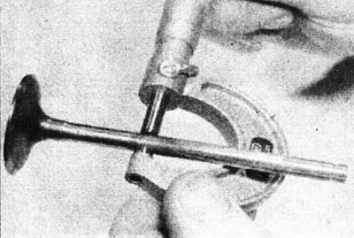
8.9 Measure the valve stem diameter.
Any significant difference in the data obtained indicates rod wear. If any of the above damage is detected, the valves must be replaced. If the valves are in good condition, or if new ones are being installed, they should be lapped onto the corresponding seat to ensure a tight seal.
10. Lapping of valves is performed as follows. Turn the cylinder head upside down, placing wooden blocks under each end to provide clearance for the valve stems.
11. Apply the appropriate grade of lapping paste to the valve seat surface and attach a suction cup to the valve head. Rotate the valve back and forth half a turn to grind the valve head against the seat, occasionally lifting the valve to redistribute the paste (see illustration).
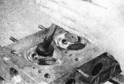
8.11. Valve grinding.
Installing a weak spring under the valve head will make the job much easier. If using a coarse grinding compound, work until the seat and valve contact surfaces become dull and matte, then wipe off the compound and repeat the process with a fine-grained compound. When the seat and valve surfaces acquire an even light gray color, lapping is considered complete. Do not grind the valves longer than necessary, this will result in unwanted seat recession into the cylinder head. Once all valves have been lapped, carefully wash off all traces of grinding compound using kerosene or a suitable solvent.
Valve components
12. Inspect the valve springs for signs of damage and discoloration, and measure their free length using calipers or a steel ruler (see illustration), or compare with a new spring.
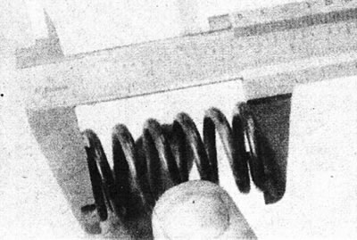
8.12. Check the free length of the valve spring.
13. Place each spring on a flat surface and check them for deformation using a square. If any of the springs are damaged, distorted or weak, purchase a new complete set of springs. It is recommended to replace the springs after each removal during an engine overhaul, regardless of their condition.
14. On F3P engines, check the tappets and adjusting washers for scratches, corrosion (especially on washers) and wear. Replace all components as necessary.
15. On Engine F7P (with 16 valves), inspect the hydraulic lifters for scratches, corrosion and wear. Replace them as needed. If new hydraulic lifters are being installed, or if the old ones have leaked oil, fill them with fresh engine oil as follows:; place the plunger in the oil with the hole facing up and, holding it with pliers, push it up and down until all the air is removed (see illustration).
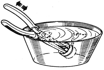
8.15 Fill the hydraulic tappet with oil - F7P engine (with 16 valves).
Rocker Arm Components - C, D, and E Series Engines
16. Inspect the rocker arm contact surfaces for pits, scratches or other signs of wear. Disassemble the rocker arm shaft and inspect the rocker arms, pivot pins and contact surfaces in the same manner. Measure the inside diameter of each rocker arm and check their placement on the shaft. Clean out the oil passages in each rocker arm using a piece of wire (see illustrations).
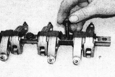
8.16a. Remove the rocker arm axle mounting bolts from the shaft...
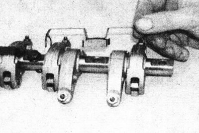
8.16b....then remove the mounting plates...
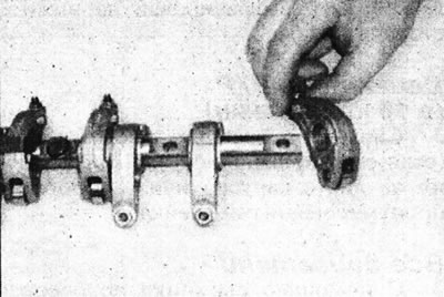
8.16s....and pull the rocker arms off the shaft, placing them in the marked containers.
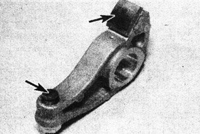
8.16d. Check the rocker arm contact surfaces (marked with arrows) for signs of wear.
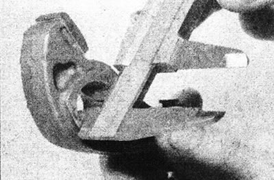
8.16e. Check the inner diameter of the rocker arms.
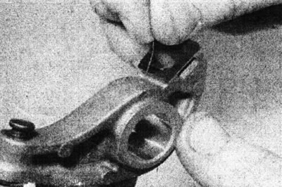
8.16f. Clean the oil holes with a piece of wire.
Replace rocker arms or axles if necessary.
17. On a D-series engine, check the condition of the rocker arm rollers. Also check that they rotate freely in the corresponding rocker arm (see illustration).
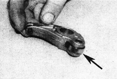
8.17. Inspect the rocker arm roller (marked with an arrow) on D-series engines.
[Source link is located on: www.RENAULTBOOK.ru]
Replace any suspected faulty rocker arms.
18. On a C-series engine, check the condition of the pushrod tips. Rolling barbells on a flat surface (for example on glass), check them for deformation.
Valve stem seals
19. Valve stem seals should be changed after each removal.