



Contents: Removal 🠛 Installation 🠛
Note: The engine and automatic transmission are removed from the engine compartment upwards and then separated. It is possible to remove it together with the sub-engine frame downwards, but this method is not described, since it requires the use of a special trolley. Before working on an engine with an automatic transmission, read the notes in Section 7B, Chapter 1. A suitable winch and lifting device will be required for the job.
Removal
1. Remove the hood as described in Section 11.
2. Remove the battery as described in Section 5A.
3. Remove the air cleaner assembly as described in the relevant Section Section 4.
4. Disconnect the oxygen sensor wiring and remove the exhaust outlet pipe. Remove the seal in the rear flange and the O-ring in the exhaust manifold flange.
5. If not already done, apply the handbrake, then jack up the front of the car and support it on axle stands. Remove both front wheels.
6. Drain the cooling system as described in Section 1.
7. Drain the transmission fluid as described in Section 1.
8. Loosen up (but don't take it off) rear bolt of the rear engine mount support fork. Loosen and remove the front bolt and move the support fork down.
9. Remove the bolts securing the drive shafts to the transmission flanges. To do this you will need a socket wrench or socket (see Section 8).
10. Refer to Section 10 and disconnect the tie rod ends from the steering knuckles.
11. One at a time on each side, loosen and remove the upper bolts securing the front suspension struts to the steering knuckles. Loosen up (but don't take it off) lower bolts.
12. Rotate the steering knuckles outward and disconnect the drive shafts from the output flanges. Tie up the drive shafts.
Models with power steering
13. Unscrew the two brackets holding the power steering hose on the electric fan bracket and the side mount bracket (see illustration).
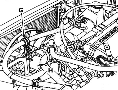
5.13. Two brackets (G and H) securing the power steering hose - models with automatic transmission.
[Material is located on the source website: renaultbook.ru]
14. Remove the power steering pump as described in Section 10. Do not disconnect the hoses and move the pump to the side.
Models with air conditioning
15. Remove the compressor and move it aside as described in Section 3, but do not disconnect the hoses and tubes.
All models
16. Remove the expansion tank, electric fan assembly and radiator together with the folded deflector. See Section 3.
17. Disconnect the fuel supply and return hoses.
18. Disconnect the brake booster vacuum hose from the intake manifold.
19. Disconnect the hoses from the intake manifold pressure sensor and the charcoal canister cleaning valve (where available).
20. Disconnect the wiring harness from the engine, or if the engine cannot be disassembled, disconnect the wiring from the junction block on the left side of the engine compartment and tie the free end to the engine. Remember all the connections. Depending on the model, the wiring connects the following components:
- Oil pressure sensor.
- Temperature sensors.
- Oil level sensor.
- Starter.
- Generator.
- High voltage central wire on the distributor cap.
- Fuel injection system.
- Ignition module.
- Ground cable on top of crossmember and automatic transmission.
- Knock sensor (where it is applied).
- Electronic ignition control unit (where it is applied).
21. As a safety precaution, remove the distributor cap as described in Section 5B.
22. Where applicable, remove the ignition module as described in Section 5B.
23. On models not equipped with air conditioning, remove the fuel injection system processor unit and disconnect the wiring from the fuel injection system relay.
24. Remove the fastener and separate the fuel injection system wiring harness from the air intake unit.
25. Disconnect the speedometer drive cable from the transmission.
26. Disconnect the accelerator pedal cable from the downshift mechanism (see illustration).
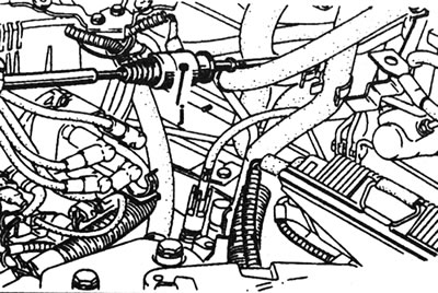
5.26. The mechanism for engaging a lower gear (J) on the gas pedal cable.
27. Remove the charcoal canister of the fuel vapor extraction system as described in Section 4D.
28. Remove the automatic transmission processor unit together with the mount.
29. Disconnect the gear selector cable.
30. Attach the winch to the lifting eyes and slightly raise the engine/transmission.
31. Unbolt and remove the left upper engine/transmission/battery bracket from the transmission and body.
32. Disconnect the right engine mount, referring to the relevant Chapter of Part WITH or D this Section.
33. Slowly lift the engine/transmission assembly out of the engine compartment, being careful not to damage surrounding components. Bring the assembly forward and lower it to the floor.
34. To separate the transmission from the engine, first unscrew the coupling bracket.
35. Loosen and remove the bolts securing the drive disc to the torque converter while holding the flywheel ring gear with a wide screwdriver.
36. Attach a homemade locking plate to the transmission clutch housing to hold the torque converter in place. A retainer plate will also be needed when installing the transmission to keep the torque converter engaged with the transmission pump.
37. Remove the starter as described in Section 5A.
38. Unbolt the transmission fluid cooler from the top of the transmission and remove the O-rings (see illustration).
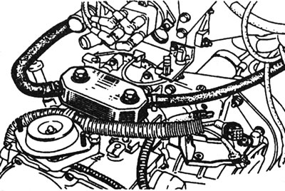
5.38. Transmission fluid cooler on top of the automatic transmission.
39. Loosen and remove the mounting nuts and bolts, and separate the transmission from the engine.
Installation
40. Perform installation in reverse order, taking into account the following notes:
- Tighten all nuts and bolts to the specified torque Specifications (where it is applied).
- When installing, use new torque converter to drive plate mounting bolts (see Specifications in Section 7B).
- When installing the front brake caliper, follow these instructions: Section 9.
- Before connecting the transmission to the engine, ensure that the torque converter is fully engaged with the transmission pump.
- Make sure the dowel pins are inserted into the cylinder block.
- Apply grease to the torque converter center bushing.
- If necessary, adjust the gear shift cable as described in Section 7B, Chapter 2.
- When installing the transmission fluid cooler, check the condition of the O-rings.
- Adjust the full throttle position - see note in Section 7B, Chapter 1.
- Fill the automatic transmission with fluid as described in Section 1 or 7B. Also check that the final drive is filled with oil.
- Fill the cooling system as described in Section 1.
- Adjust the gas pedal cable.