



Contents: Fuel vapor extraction system 🠛 Carburetor engines 🠛 Fuel injection systems for D-series…🠛 Fuel injection systems for E-series…🠛 F3P and F7P engines (with 16 valves) 🠛 Crankcase gas neutralization system 🠛 Exhaust gas neutralization system 🠛 Catalytic Converter - Precautions 🠛
Fuel vapor extraction system
1. The fuel vapor extraction system is designed to minimize the emission of fuel vapor. The fuel filler cap and hoses are part of this system. The rest of the system may vary depending on the model (see illustration).
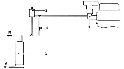
1.1 Typical layout of fuel vapor removal system components - F3P engine with central fuel injection: 1 - Intake manifold; 2 - Solenoid valve; 3 - Coal canister; 4 - Limiter; A - Deflector; R - Pipe from the fuel tank.
Carburetor engines
2. Carburetor models are equipped with a separator and a steam accumulator.
3. Fuel vapor that forms in the carburetor float chamber when the engine is turned off is collected in the vapor accumulator. The trap intercepts steam generated in the fuel supply line and returns it to the fuel tank.
Fuel injection systems for D-series engines
4. Fuel vapor is collected in a canister installed under the right headlight. When the engine is running, steam is supplied to the intake manifold. The solenoid valve on the front left side of the engine controls the cleaning of the charcoal canister.
Fuel injection systems for E-series engines
5. Fuel vapor is collected in a canister installed under the right headlight.
When the engine is running, steam is supplied to the intake manifold. The solenoid valve on the front left side of the engine controls the cleaning of the charcoal canister.
F3P and F7P engines (with 16 valves)
6. The system is similar to the one described above for E-series engines, but it also uses a limiter (or limiters, depending on the model). The solenoid valve is located behind the right headlight.
Crankcase gas neutralization system
7. The system ensures the presence of vacuum in the crankcase, which prevents oil contamination, smoke and oil leaks through the seals.
8. The location of the crankcase ventilation system components may vary depending on the engine type (see illustrations).
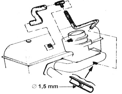
1.8a. Crankcase ventilation hoses and restrictor - C-series engine.
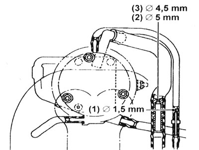
1.8b. Crankcase ventilation hoses and restrictors - E-series engines.
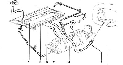
1.8 sec. Crankcase ventilation hoses and restrictors - F7P engine (with 16 valves): 1 - Valve cover; 2 - Hose (from the throttle valve); 3 - Hose (to the throttle valve); 4 - Intake manifold; 5 - Limiter (diameter 1.7 mm); 6 - Limiter (diameter 5.5 mm).
9. When the engine is idling or at part load, due to the high vacuum in the intake manifold, crankcase gases are sucked through a calibrated restrictor into the combustion chambers.
10. Crankcase ventilation hoses and restrictors must be cleaned periodically to ensure proper functioning of the system.
Exhaust gas neutralization system
11. All models with fuel injection, except early ones with F7P engine (with 16 valves), equipped with an oxygen sensor and a catalytic converter. With the help of these components, a very low level of toxic impurities in the exhaust gas is achieved.
12. Oxygen sensor also known as "lambda" sensor (the name comes from the symbol used to indicate the air-fuel ratio) is located in the exhaust outlet pipe. It sends a signal to the injection system's processor unit. This signal changes depending on the oxygen content in the exhaust gas. The processor uses the signal to calculate the amount of fuel that should be injected to ensure efficient combustion and low emissions.
13. The oxygen sensor contains an electric heater that is energized when the ignition is turned on. This way, the sensor quickly warms up to operating temperature (over 250°C), and during the warm-up period the amount of emissions is reduced.
14. The catalytic converter is located in the exhaust system at the end of the tailpipe. It contains a ceramic element coated with a precious metal compound. This composition acts as a catalyst, facilitating the conversion of carbon monoxide (CO) to carbon dioxide (CO₂), and unburned hydrocarbons (HC₂) to water and carbon dioxide (H₂O and CO₂).
Catalytic Converter - Precautions
15. The catalytic converter is a reliable and simple device that does not require any maintenance in itself, but there are some recommendations that the car owner must follow to ensure that the converter functions properly throughout its entire service life.
Gasoline models
a) DO NOT use leaded gasoline in a vehicle equipped with a catalytic converter, this will reduce conversion efficiency and eventually cause converter failure.
b) Always maintain the ignition system and fuel system in good condition.
c) If the engine misfires, do not operate the vehicle at all (or at least as little as possible) until the damage is repaired.
d) DO NOT attempt to tow-start the vehicle - the catalytic converter will become soaked with unburned fuel, which may cause the engine to overheat after starting.
e) DO NOT turn off the ignition at high engine speeds.
f) DO NOT use fuel or motor oil additives - they may contain substances harmful to the catalytic converter.
g) DO NOT operate the vehicle if the engine is observed to be burning oil (blue smoke).
h) Remember that the catalytic converter operates at very high temperatures. DO NOT park your car on dry leaves or long grass.
I) Remember that the catalytic converter is FRAGILE - do not hit it with tools during servicing.
j) In some cases, a hydrogen sulfide smell may be felt from the exhaust system (like the smell of rotten eggs): This is normal for many vehicles equipped with a catalytic converter. After several thousand kilometers the problem should disappear.
k) The service life of a catalytic converter on a well maintained vehicle should last between 80,000 and 160,000 kilometers - if the efficiency of the converter is reduced, replace it.
Diesel models
See information given above in points f, g, h and i for petrol engine models.
Original of this article on the website [RENAULTBOOK.ru]