



Contents: Fuel vapor extraction system for…🠛 Fuel Injected Models - Check 🠛 Fuel Injected Models - Canister…🠛 Replacing the solenoid valve 🠛 Crankcase gas neutralization system 🠛 Exhaust gas neutralization system 🠛 Oxygen sensor - replacement 🠛 Catalytic converter replacement 🠛
Fuel vapor extraction system for carburetor models
1. There are no specific test procedures for carburetor fuel vapor removal system components. Periodically check the condition and reliability of the connections of the various hoses.
2. If necessary, replace faulty components.
Fuel Injected Models - Check
3. The basis of the system's operation is that the electromagnetic valve should be open only when the engine is warm and the throttle valve is not closed. The following procedure is based on information regarding the F7P engine (with 16 valves), but it will be fair for others as well.
4. Warm up the engine to normal operating temperature, then turn it off. Attach a vacuum gauge (range 0 - 1000 millibars) to the hose between the canister and the restrictor. Connect the voltmeter to the solenoid valve terminals.
5. Start the engine and let it idle. The instrument should not show vacuum and there should be no supply voltage to the solenoid valve.
6. If the instrument registers manifold vacuum but there is no voltage at the valve, make sure the restrictor is the correct size. If everything is OK, the solenoid valve is stuck in the open position.
7. If voltage is present in idle mode, then the wiring or processor unit is faulty.
8. Press the gas pedal lightly. Voltage should immediately appear at the terminals of the solenoid valve, and the device will register a manifold vacuum.
9. If there is no vacuum even though there is power to the valve, there may be a leak in the hoses or the valve may not open.
10. If there is no voltage, the wiring or the processor unit is faulty.
Fuel Injected Models - Canister Replacement
11. Unscrew the two screws securing the front right wheel arch liner and move the liner to the side. Loosen the fastening strap and release the canister (see illustration).
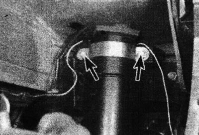
2.11 To release the tie, loosen the screws (marked with arrows).
12. Disconnect the hoses from the canister, remembering their connection points (see illustration).
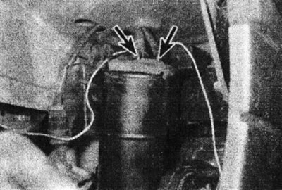
2.12. Carbon canister hoses (marked with arrows).
(Access to the hoses can be improved by removing the right headlight.)
13. Dispose of the old can properly, remembering that it may contain fuel in liquid and/or vapor form.
14. Install in reverse order. Make sure the hoses are connected correctly.
Replacing the solenoid valve
15. Disconnect the hoses from the solenoid valve, noting their location (see illustration).
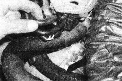
2.15. Disconnect the vacuum hose from the solenoid valve - D-series engine.
16. Disconnect the wiring connector from the valve. Remove the valve from the bracket (on D-series engines, unscrew the valve from the engine mounting lug).
17. Install in reverse order. Make sure the hoses are connected correctly.
Crankcase gas neutralization system
Checking the serviceability
18. There are no specific testing procedures for the components of the crankcase ventilation system. Periodically check the condition and reliability of the connections of the various hoses.
Replacement of components
19. Mark the hoses before disconnecting them to avoid confusion during installation.
Exhaust gas neutralization system
20. The remainder of this Chapter applies to fuel injected models equipped with an oxygen sensor and catalytic converter.
Checking the serviceability
21. An exhaust gas analyzer is required for this work (cO meter). The ignition system must be in good condition, the air cleaner element must be clean, and the engine must be in good working order.
22. Warm up the engine to normal operating temperature, then connect the exhaust gas analyzer according to the manufacturer's instructions.
23. Run the engine at idle speed and check the CO level (see Specifications in Parts B or Parts C this Section). Repeat the test at an engine speed of 2500-3000 rpm. If the CO level matches the data specified in the Specifications, the system works correctly.
24. If the CO level is above normal, disconnect the oxygen sensor wiring. If the CO level rises when the sensor is disconnected, then the oxygen sensor is OK and the catalytic converter is most likely defective. If disconnecting the sensor does not affect the CO level in any way, then the sensor itself is faulty.
25. If you have a digital voltmeter, you can measure the output voltage of the oxygen sensor (terminal C of the sensor connector, or terminal 35 of the processor unit connector). The voltage should jump between 625 - 1100 mV (rich mixture) and 0-100 mV (lean mixture).
26. If the vehicle has been accidentally filled with leaded gasoline, run it through several tanks of unleaded gasoline before replacing any component. Then check if the CO level has decreased.
Oxygen sensor - replacement
Note: When installing a new sensor, a suitable high temperature anti-lock compound will be required.
27. Working under the vehicle, disconnect the sensor wiring (see illustration).
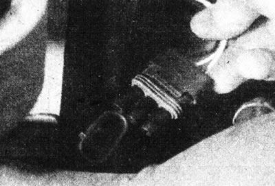
2.27. Disconnect the oxygen sensor wiring.
28. Release the heat-insulating shield from the fasteners. Unscrew the sensor from the outlet pipe and remove it (see illustrations).
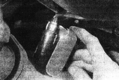
2.28a. Release the heat-insulating shield from its mountings...
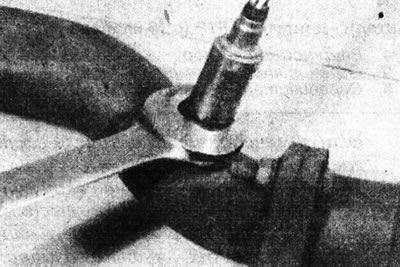
2.28b....then unscrew the oxygen sensor...
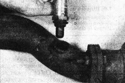
2.28s....and remove it from the exhaust pipe.
29. Clean the threads in the exhaust pipe and the threads on the sensor (if it will be used).
30. Please note that if the wiring is damaged, the sensor must be replaced.
31. Coat the sensor threads with a high temperature anti-lock compound. Screw the sensor in by hand and then tighten it completely.
32. Connect the sensor connector.
Catalytic converter replacement
33. The catalytic converter is replaced in the same way as any other part of the exhaust system. Cm. Part B or Part C this Section, depending on the model.