



2. Apply the handbrake, then jack up the front right corner of the car until the wheel is off the ground. Support the vehicle with axle stands and engage 5th gear. In this way, the engine can be easily turned by rotating the right wheel. Alternatively, use a wrench to turn the engine over the crankshaft pulley bolt.
3. Rotate the crankshaft to set piston No. 1 to TDC on the compression stroke and insert the dowel pin to check the position of the crankshaft.
4. Cover the generator with a plastic bag or cloth.
Models with Lucas fuel pump
5. Now you will need a micrometer with a dial and a special probe (renault Mot tool. 1079) (see illustration).
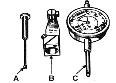
15.5 Tool kit for adjusting injection timing on Lucas pump - Renault Mot. 1079: A - Probe; B - Adapter; C - Micrometer.
6. Remove the inspection plug from the top of the pump and remove the sealing washer. Insert the probe into the hole so that its tip rests on the mounting protrusion of the rotor (see illustrations).
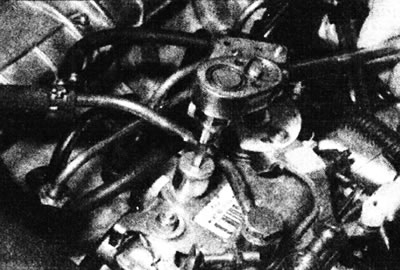
15.6a. Unscrewing the plug of the installation hole on the top of the Lucas pump.
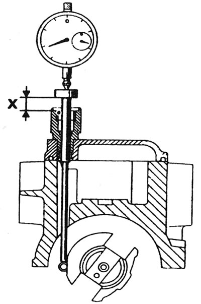
15.6b. Checking injection timing (renault Mot tool. 1079) - Lucas pump - X = Injection point marked on the pump.
7. Place the dial micrometer on the fuel pump body. The micrometer should be positioned on the probe so that its plunger is located at the middle of its stroke.
8. Remove the dowel pin, then rotate the crankshaft approximately a quarter turn counterclockwise and reset the micrometer reading to zero. Make sure the probe is positioned on the surface of the mounting hole sealing washer.
9. Slowly turn the crankshaft clockwise (returning the engine to TDC), until the locating pin is seated again.
10. Read the micrometer reading; the result obtained must correspond to the value indicated on the label on the pump cover.
11. If the result obtained does not correspond to the data provided, proceed as follows.
12. Unscrew and remove the toothed drive belt cover from the fuel pump sprocket.
13. Remove the probe and lock the pump pulley with the special tool Renault Mot. 1200-01 (see Chapter 13).
14. Fuel pump pulley type "MAA" (Micrometric Angle Adjustment) consists of a hub/plate and a gear frame, which are fastened together by a central bolt (left-hand thread) (see illustration).
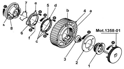
15.14 Design of the MAA type sprocket: 1 - Central bolt - left-hand thread; 2 - Pulley plate; 3 - Pulley nut*; 4 - Toothed pulley rim; 5 - Injection timing correction ring; 6 - Angular adjustment ring; 7 - Central bolt locking spring; 8 - Pulley hub; A - Counterclockwise movement is the reason for installing the tool; B - Transverse movement of rings; C - Clockwise rotation, appearing on the pump shaft; a - Thread for "d"; b - Straight recesses for the guide protrusions "e"; c - Grooves for tool pins;
d - Thread for "a"; e - Guide tabs; f - Beveled guides for "h"; h - Beveled guides for "f".
*Non-ferrous metal nut with built-in washer
The plate has three holes for a special tool (Renault Mot. 1358 for the "MAA" pulley and the "HTD" toothed drive belt or Mot. 1358-01 for the "HTD2" toothed drive belt), which is used to rotate the pump shaft. But first, the central bolt is loosened using the Renault Mot. 1359 tool (see illustration 13.33).
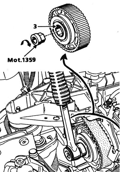
13.33. Unscrewing the central bolt "3" of the MAA type sprocket using a special Renault tool - the bolt has a left-hand thread (lucas pump).
15. Install the special tool into the three holes and turn the plate so that the three pins of the tool enter the three slots in the timing ring (see illustration).
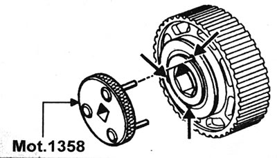
15.15. Renault tool for rotating the MAA sprocket plate.
Note: Tool Mot. 1358 is designed for the "MAA" sprocket and the "HTD" toothed drive belt. If the "HTD2" belt is installed, tool Mot. 1358 must be modified, or use tool Mot. 1358-01
16. Now rotate the tool/plate assembly clockwise until the tool locks. This will position the pulley to begin adjustment.
17. Remove the pulley locking tool and rotate the crankshaft 2 turns (setting piston #1 back to TDC) until the tool can be inserted again.
18. Now turn tool Mot. 1358 or Mot. 1358-01 counterclockwise until the correct injection timing is obtained on the micrometer. If the injection timing exceeds the specified value during installation, turn the tool back 0.7 mm below the value before repeating the adjustment.
19. Remove the special tool, then tighten the center bolt (left-hand thread) tightening torque of 20 Nm using tool Mot. 1359.
20. Remove the dowel pin.
21. Install tool Mot. 1200-02 to lock the pulley. Rotate the crankshaft manually counterclockwise until the locking tool contacts the pulley.
22. Tighten the central bolt to a tightening torque of 90 Nm using tool Mot. 1359.
23. Remove the pulley locking tool, turn the crankshaft 2 revolutions, and recheck the pump injection timing setting.
Caution: If the correct injection timing cannot be established, check the camshaft sprocket and fuel pump adjustment. The position is considered correct if all timing marks are well aligned and if there are exactly 30 teeth from the mark on the camshaft sprocket to the mark on the fuel pump sprocket.
24. Once the injection timing is set correctly, remove the micrometer. Remove the probe from the hole and install the plug with the sealing washer.
25. Connect the fuel lines of the injectors to the pump, securely tightening the connecting nuts.
26. Remove the plastic bag covering the generator.
27. Lower the car to the ground and connect the negative cable to the battery.
28. Fill and bleed the fuel system (see Chapter 7).
29. Check and, if necessary, adjust the idle speed and deceleration speed (see Chapter 18).
(Material is located on the source website: RenaultBook.ru)
Engine with Bosch fuel pump
30. You will need a micrometer with a dial, a special probe and an adapter that screws into the hole at the end of the pump (renault Mot tool. 856) (see illustration).
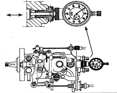
15.30 Micrometer and probe for use with Bosch pump.
31. Unscrew the connecting nuts securing the injector pipes to the high-pressure fuel pump. Cover open couplings to prevent dirt from entering.
32. Unscrew the plug on the left side of the fuel pump, between the injector tube connections.
33. Insert the probe and connect it to the micrometer placed directly in front of the hole.
34. Remove the dowel pin and rotate the crankshaft approximately a quarter turn counterclockwise, then reset the micrometer reading to zero. To do this, apply the handbrake, then jack up the front right corner of the car until the wheel is off the ground. Support the car with axle stands and engage 5th gear. In this way, the engine can be easily turned by rotating the right wheel. Alternatively, use a wrench to turn the engine over the crankshaft pulley bolt.
35. Slowly turn the crankshaft clockwise (setting the engine back to TDC), until the dowel pin can be reinserted.
36. Read the micrometer reading; the result obtained must correspond to the data given in Specifications. Please note that the injection point is also marked on the pump throttle lever.
37. If the result obtained does not correspond to the data provided, proceed as follows:
38. Loosen the three bolts of the right pump hanger and the nuts of the left pump hanger, then slowly rotate the pump body until you find the position where the micrometer shows the value specified in Specifications. Then tighten the mounting nuts and bolts, making sure that the reading on the micrometer does not change.
39. Remove the dowel pins and turn the crankshaft one and three quarter turns clockwise. Make sure the micrometer reads zero.
40. Slowly turn the crankshaft clockwise (setting piston No. 1 to TDC) until the dowel pin can be reinserted. Recheck the injection timing value.
41. If adjustment is necessary, loosen the pump mounting nuts and bolts and repeat steps 38-40.
42. Once the injection timing has been correctly set, remove the micrometer, probe, and install the plug, tightening it to the tightening torque specified in the Specifications. Tighten the three bolts of the right pump hanger and the nuts of the left pump hanger to the specified tightening torque Specifications.
43. Connect the fuel injector tubes to the pump and tighten the union nuts securely.
44. Remove the plastic bag from the generator.
45. Remove the dowel pin.
46. Lower the car to the ground and connect the negative cable to the battery.
47. Fill and bleed the fuel system as described in Chapter 7.
48. Check and, if necessary, adjust the idle speed and deceleration speed.