



Contents: Removal 🠛 Installation 🠛
Note: Be careful not to allow dirt to enter the pump or injector tubes. When installing, use new O-rings on the fuel line banjo connections.
Removal
1. On engines with air conditioning, proceed as follows.
2. To gain access to the fuel pump mounting bolts, you need to remove the generator and its bracket.
3. Disconnect the negative cable from the battery.
4. Remove the generator as described in Section 5A, then proceed as follows.
5. Loosen the mounting bolts and remove the power steering pump pulley from the pump drive flange. Please note that you must hold the pulley while loosening the bolts (for example, using an old drive belt).
6. Unscrew the mounting bolts and remove the bracket with the auxiliary drive belt guide roller.
7. Remove the two upper bolts securing the air conditioning compressor to the generator bracket.
8. Apply the handbrake, then jack up the front of the car and place it on axle stands. Where present, remove the lower engine shield.
9. Remove the right front wheel and wheel arch liner.
10. Loosen the lower A/C compressor mounting nuts and bolts, then rotate the compressor downward so the alternator bracket can be removed from the top.
11. For all models, proceed as described in the following points.
12. If not already done, disconnect the negative cable from the battery.
13. Unscrew and remove the right upper engine mount cover.
14. Rotate the crankshaft to set piston No. 1 to TDC on the compression stroke and insert the dowel pin to check the position of the crankshaft.
15. Loosen the mounting bolts and remove the timing belt cover that covers the fuel pump sprocket.
16. If there is a tool for holding the fuel pump pulley (Renault Mot. 1200), remove the dowel pin, rotate the crankshaft from TDC by one tooth of the camshaft pulley, and insert a holding tool into the fuel pump pulley (see illustration).
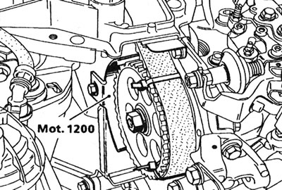
13.16. Renault tool for holding the pulley in a stationary position.
17. If the specified tool is not available, remove the toothed drive belt.
18. Disconnect the accelerator pedal cable from the fuel pump, see Chapter 5 if necessary.
19. On engines with a thermally controlled fast idle, disconnect the fast idle cable from the fuel pump, see Chapter 9 if necessary.
20. On models with a vacuum-operated fast idle drive, disconnect the cable from the pump lever and the vacuum hose from the drive (see Chapter 10).
21. Loosen the banjo connection bolt and disconnect the fuel supply hose from the fuel pump. Cap the open end of the hose or pipe and plug the outlet on the fuel pump to prevent dirt from entering. Do the same with the main return hose (see illustrations).
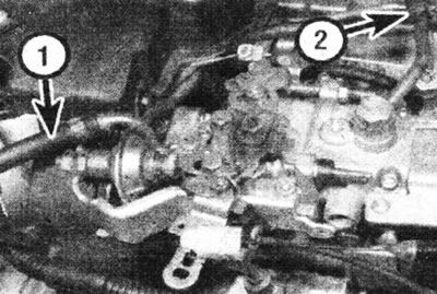
13.21a. Fuel supply hose "1" and main return hose "2" - Bosch pump.
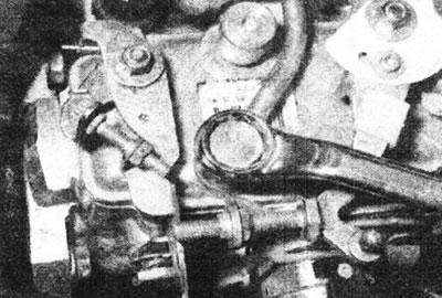
13.21b. Disconnecting the main fuel return line coupling - Lucas pump.
22. Disconnect the main fuel return hose from the fuel injector (see illustration).
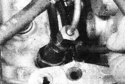
13.22. Disconnecting the main return fuel line from the fuel injector.
23. Where applicable, disconnect the auxiliary fuel return hose from the pump.
24. Disconnect all electrical wiring from the pump. Please note that on some pumps this can be done by simply disconnecting the wiring from the connectors on the pump. Some pumps require disconnecting wiring from individual components (some connections may be protected by rubber sheaths) (see illustration).
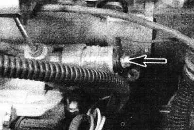
13.24. Electrical wiring terminal on the ALFB valve winding - Bosch pump.
On engines with Lucas pumps, disconnect the wiring from the following units: coded solenoid valve, injection timing corrector, and throttle lever potentiometer.
25. Unscrew the connecting nuts securing the tubes to the fuel pump and injectors. Remove the tubes as an assembly. Cover open couplings to prevent dirt from entering. Please note that the fuel injector outlet hoses must be removed to allow the injectors to be capped (see illustration).
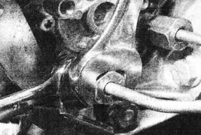
13.25. Unscrewing the connecting sleeve of the injector tube on the pump.
26. Where applicable, remove the plastic generator shield below the fuel pump. Note the location of the brackets attached with nuts and bolts.
27. Then proceed as follows:
28. Unscrew the fuel pump pulley mounting nut and remove the washer. If there is no tool to hold the pulley (see illustration 13.16), lock the pulley with a homemade tool inserted into the holes in the pulley (but not into the pulley teeth).
29. Mark the position of the sprocket relative to the end of the pump shaft. This must be done regardless of whether the timing belt has been removed or not, as the pulley has two slots for the woodruff key (for use with various types of fuel pumps).
30. Fit the Renault special tool (Mot. 1053) to the pump sprocket and release the pulley from the pump shaft (see illustration).
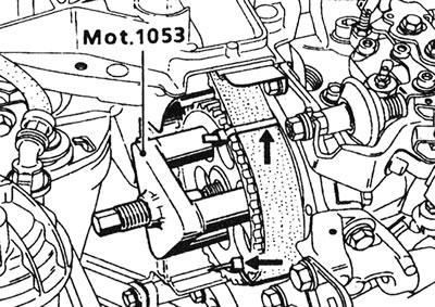
13.30 Removing the Bosch pump sprocket using the special Renault tool - note the two plastic ties (arrows) securing the toothed drive belt.
Before removing the pulley, we recommend securing the timing belt using two plastic ties.
Note: The puller should be positioned in the pulley holes, not on the teeth. For the MAA pulley, you will need a special puller that is installed on the pulley hub.
31. Remove the puller. If the fuel pump pulley holding tool is installed and the timing belt has not yet been removed (see point 16 above), do not remove the pulley.
32. Proceed as follows:
Warning: On early versions of these engines, the "MAA" pulley is attached to the fuel pump shaft with a regular nut and a separate washer. A special Renault puller will be required (Mot. 1357 - see paragraphs 33-40 below), which is located on the pulley hub. On later versions of these engines, the MAA pulley is secured to the fuel pump shaft with a non-ferrous metal nut and washer that acts as a puller. The pulley can be released from the pump shaft by loosening the nut. Before starting work, carefully determine the method of attaching the pulley.
33. Using the Renault special tool (Mot. 1359), remove the sprocket center bolt with plate: the bolt has a left-hand thread (see illustration).
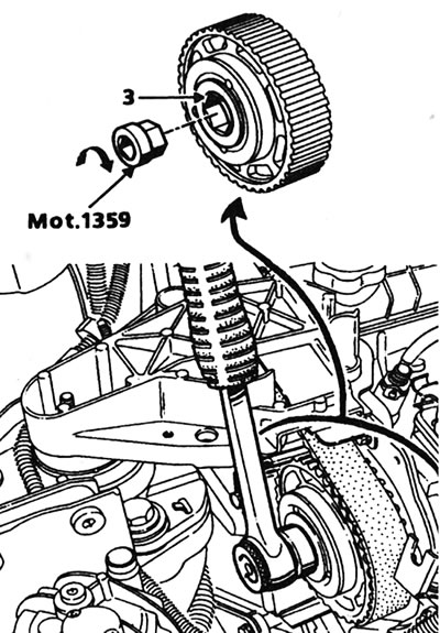
13.33. Unscrewing the central bolt "3" of the MAA type sprocket using a special Renault tool - the bolt has a left-hand thread (lucas pump).
34. Screw the Renault special tool (Mot. 1357) into place of the central bolt. Then screw a 40 mm long M12x125 bolt into the tool to release the pulley (see illustration).
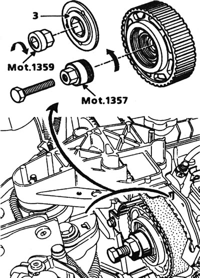
13.34 Removing the Lucas MAA pump sprocket using the Renault special tool and a 12mm bolt - early F8Q engine.
35. On all models, remove the bolts and nuts securing the left fuel pump mounting bracket to the cylinder head (see illustration).
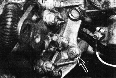
13.35. Unscrew the bolts and nuts securing the left pump suspension bracket - Lucas pump.
36. Once again, make sure that all pipes, hoses and wires are disconnected from the pump.
37. Place alignment marks on the pump and bracket. This will help when installing the pump.
38. Unscrew the three mounting bolts and remove the pump from the bracket, leaving the pulley with the toothed drive belt in place (see illustrations).
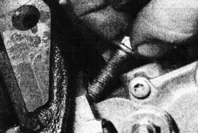
13.38a. Remove the bolts from the right pump mount...
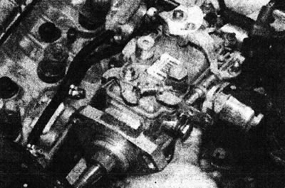
13.38b....and get the pump - Lucas.
On F8Q 620 engines, the lower mounting bolt is most easily accessed from the left side of the pump. This procedure will require a special Renault tool (Mot. 902-02). If you don't have one, use a deep socket and an extension rod. On engines with a Lucas pump and a MAA pulley, loosen the bolts with a T40 socket wrench, the minimum length of which should be 60 mm, and move the pump back.
39. Remove the woodruff key from the end of the pump shaft if it is loose.
40. If necessary, you can unscrew the left pump mount bracket and the gas pedal cable bracket from the pump.
Installation
41. Where applicable, attach the left pump mount bracket and throttle pedal cable bracket to the pump.
42. Begin installation by placing the woodruff key on the end of the pump shaft. On F8Q 784, 786 and 788 engines, the key must be inserted into the slot aligned with the outlet axis of the cylinder #1 injector (see illustration).
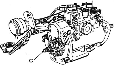
13.42. The woodruff key on the pulley must be aligned with the "C" output for injector No. 1 - Lucas pump.
On all engines, ensure the pump shaft is completely dry.
43. Install the pump on the right bracket. If the pulley is in place, insert the pump shaft into the pulley. Align the marks made on the pulley and pump shaft. On the F8Q 620 engine, ensure the woodruff key is inserted into the right-hand slot in the pulley (see illustration).
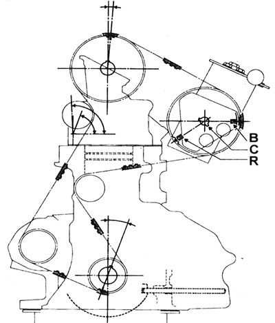
13.43. Position of timing marks on the camshaft and fuel pump pulleys (cylinder No. 1 at TDC) - F8Q 620 engine: B - Timing mark on the pulley for the Bosch fuel pump; C - Slot for a woodruff key; R - Timing mark on pulley for Lucas fuel pump.
44. Where applicable, align the marks made on the pump and right-hand bracket, or if installing a new pump, re-draw the mark from the old pump to ensure approximate fitment.
45. Install and lightly tighten the right pump hanger bolts. On the F8Q 620 engine, access to the lower mounting nut can be improved by removing injector #4 (see Chapter 17). Install the bolts and nuts securing the left fuel pump bracket to the cylinder head and tighten them, but not too tight.
46. On the F8Q 620 engine, install the washer, then tighten the pump sprocket retaining nut to the torque specified in the Specifications, locking the pulley as during removal (see illustration).
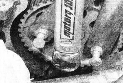
13.46 Using a homemade tool to hold the pump pulley while tightening the mounting nut.
47. On F8Q 784, 786 and 788 engines, install the sprocket centre bolt using the Renault Mot. 1359 special tool (see illustration 13.33), and tighten it to a torque of 90 Nm. Using the special Renault tool used during removal, lock the pulley and install the retaining nut, tightening it to the tightening torque specified in the Specifications.
48. On all engines, if the timing belt has been removed, install and tension it.
49. Where used, remove the holding tool from the sprocket, then set piston #1 to TDC on the compression stroke.
50. Check and adjust the injection timing as described in Chapters 15 or 16.
51. Install a plastic shield under the pump.
52. Install and connect the fuel lines of the injectors, and tighten the connecting couplings.
53. Connect all electrical wiring to the pump.
54. Connect the fuel feed and return lines and hoses and tighten the banjo bolt to the torque specified in the Specifications. Use new sealing washers. Also connect the drain hoses.
55. Connect the gas pedal cable and adjust it as described in Chapter 5.
56. On F8Q 620 engines with air conditioning, reverse the steps 1-10. Install and tension the accessory drive belt.
57. Where applicable, on models with a thermally actuated fast idle control, connect and adjust the fast idle cable as described in Chapter 9, but remember that the final adjustment should be made after the engine has reached normal operating temperature.
58. On models with a vacuum-operated fast idle speed control, connect the hose to the control and check the fast idle speed control cable length adjustment as described in Chapter 10.
59. Install the timing belt cover onto the fuel pump sprocket and the upper right engine mount cover, and tighten the bolts securely.
60. Check the adjustment of the "no load" switch.
61. Connect the negative cable to the battery.
62. Fill and bleed the fuel system as described in Chapter 7.
63. Start the engine and check the idle speed and deceleration speed.