



Note: Engine mounts are precisely located when the vehicle is manufactured at the factory. Before removal, it is important to mark the exact position of each hanger to ensure proper engine/gearbox placement.
Inspection
1. Apply the handbrake, then jack up the front of the car and place it on axle stands.
2. Visually inspect the rubber mounts on the engine/transmission mounts for cracks and dirt. Determine the condition of the rubber cushions. If there is excessive suspension movement, or if the rubber condition has deteriorated, the suspension should be replaced.
Replacement
Right suspension
3. Unscrew the screw and remove the plastic cover from the top of the hanger (see illustrations).
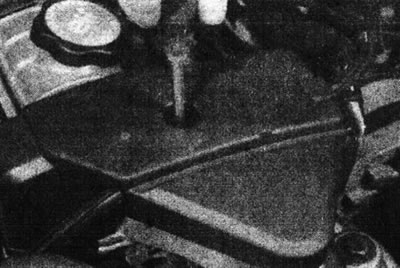
18.3a. Unscrew the screw...
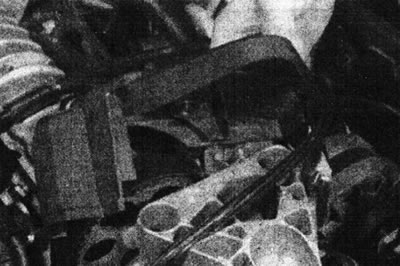
18.3b....and remove the cover - engine F3P.
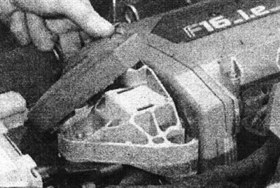
18.3s. Remove the cover...
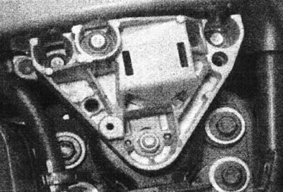
18.3d....to gain access to the upper mount nuts - F3P engine (with 16 valves).
4. Mark the position of the hanger with paint.
5. Unscrew the nut and remove the washer.
6. Support the weight of the engine by hooking a winch to the right mounting eye or by placing a jack and a block of wood under the pallet.
7. Unscrew the upper bracket from the drive cover bracket at the end of the cylinder head.
8. Unscrew the lower mount bracket and the movement limiter from the body (see illustration).
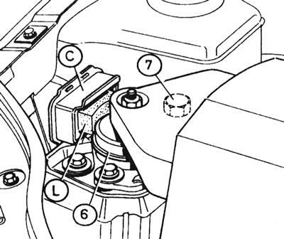
18.8. Right engine mount: C - Corps; K - Vertical movement limiter; 6 - Rubber cushion; 7 - Longitudinal movement limiter.
9. Install the new components in the reverse order of removal, but do not tighten the mounting nuts and bolts. Finally, perform the hanger adjustment procedure as described later in this Chapter.
Transmission bracket
10. Remove the battery as described in Section 5A.
11. Support the transmission with a jack or winch.
12. Mark the position of the hanger with paint.
13. Remove the center nut and two nuts securing the support mounting pad to the top bracket (see illustration).
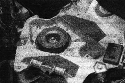
18.13. Central nut and mounting nuts of the gearbox suspension shoe.
14. Unscrew the upper bracket from the body and remove the support mounting pad (see illustrations).
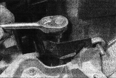
18.14a. Remove the rear bolt from the upper gearbox bracket.
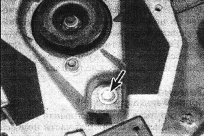
18.14b. Front gearbox upper bracket bolt (marked with an arrow).
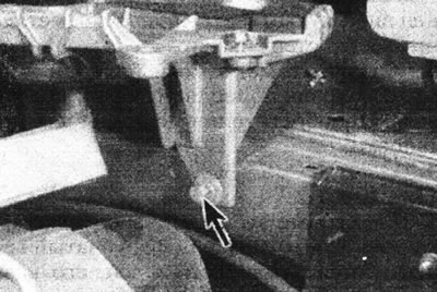
18.14s. Lower bolt of the upper gearbox bracket (marked with an arrow).
Original article is on the portal (RENAULTBOOK)
15. If necessary, unscrew the lower bracket from the transmission.
16. Install in reverse order, but do not tighten the mounting nuts and bolts. Finally, perform the hanger adjustment procedure as described later in this Chapter.
Rear suspension/lower link
17. Working under the vehicle, remove the bolts securing the rear suspension support fork to the brackets on the engine subframe and cylinder block. Remove the connection from under the car.
18. If necessary, unscrew and remove the brackets.
19. Install in reverse order, but do not tighten the bolts. Finally, perform the hanger adjustment procedure as described later in this Chapter.
Adjustment
20. If only one hanger is being replaced, install the new one in the same position as the old one. If multiple hangers have been replaced, slightly raise the engine on the winch, loosen all mounting bolts and perform the following procedure.
Transmission bracket
21. Using illustration 14.21 from Parts From This Section, tighten the upper nut (I) and the lower mounting bolt (II) to a torque of 3 Nm. Tighten the two upper mounting bolts (III) to a torque of 20 Nm, then re-tighten the nut (I) and bolt (II) to a torque of 3 Nm.
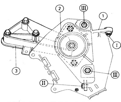
14.21. Transmission bracket components and their adjustment. I, II and III see in the text: 1 - Upper suspension/platform for battery; 2 - Rubber cushion; 3 - Transmission bracket (lower).
22. With the transmission bracket, lower bracket and right hanger in the operating position, make sure the mounting bolts are loose.
23. Remove the right front wheel, then remove the plastic panel from the wheel arch to gain access to the crankshaft pulley. On 8-valve engines, ensure there is at least 36.5 mm of clearance between the crankshaft pulley and the edge of the body next to the rod (models without power steering) or not less than 34 mm (models with air conditioning or power steering) (see illustration).
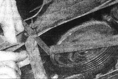
18.23. Checking the clearance between the crankshaft pulley and the reinforcing rod when adjusting the position of the engine mount.
On 16-valve engines, ensure there is at least a 29 mm gap between the plastic cover on the crankshaft pulley and the edge of the body near the crankshaft. Note that this gap does not include the thickness of the straightedge applied to the pulley.
24. Maintaining this gap, center the transmission bracket shoe longitudinally in the upper battery bracket/platform. Tighten the mounting nuts and bolts.
Right suspension
25. Unscrew the top bracket if it was installed in place. Measure the distance between the outer edge of the travel limiter housing and the center of the mounting stud (see illustration).
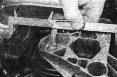
18.25. Checking the distance between the outer edge of the travel limiter housing and the center of the stud.
26. Install the upper bracket and tighten the mounting bolts to the specified tightening torque Specifications.
27. With the lower mount bracket and travel limiter bolts loose, lower the winch until the engine/transmission rests on the hangers. Measure again the distance between the outer edge of the travel limiter housing and the center of the mounting stud (see illustration 18.25). Adjust the suspension if necessary. Tighten the two lower bracket bolts to the specified torque Specifications.
28. Leaving the bolts free, center the stop within the hole in the top bracket so that there is an equal gap on both sides. Tighten the limiter mounting bolts to the specified tightening torque Specifications.
29. Working under the vehicle, install the rear suspension support fork and tighten the bolts to the specified tightening torque Specifications.
30. Check the distance specified in point 27 on the right suspension and adjust if necessary.