
English Русский
Български
Беларускі
Український
Српски
Hrvatski
Română
Polski
Slovenský
Magyar
Bookmark Contacts Articles Sitemap
Company vehicles Peugeot Company vehicles Opel Company vehicles Skoda Company vehicles Land Rover Company vehicles Mitsubishi Company vehicles Volkswagen Company vehicles Honda
RenaultBook.ru


Duster   Fluence   Kangoo   Laguna   Logan   Megane   Sandero   Scenic   Symbol   Clio   Other
Renault 19 (1988-1996) Espace I and II (1984-1996) Espace III (1996-2002)

Cylinder head and valves — removal and installation (engine in a car) (Renault Espace I)

  • Main
  • Renault
  • Espace I and II (1984-1996)
  • Power unit
  • Engine repair
  • Cylinder head and valves — removal and installation (engine in a car)
0
Contents: V6 Engine 🠛 Petrol 4-cylinder engine 🠛 Turbocharged diesel engine 🠛
1. The process of removing the cylinder head has already been described when disassembling an engine removed from a vehicle. The following text provides a short description of the situation if it is necessary to remove only the cylinder head, for example to replace the cylinder head gasket or to repair it.

V6 Engine


2. To carry out work without removing the camshaft drive cover, you must have a special tool (mot. number 589). If you do not have this tool, remove the camshaft drive cover. The work is approximately the same on the left and right heads. Any differences will be noted.

3. Disconnect the negative battery cable and drain the coolant from the cooling system.

4. Disconnect all wiring and hoses from the cylinder head. Remove the air cleaner, wiring, intake manifold, alternator, crankcase ventilation hose, cylinder head cover, camshaft sprocket bolt plug or camshaft drive cover. On the left cylinder head, loosen the power steering pump drive mechanism and remove the pump pulley. On the right cylinder head, remove the dipstick tube bracket, center plug socket and distributor.

5. Turn the crankshaft until the dowel pin (1) (see illustration) will not be at the top, and unscrew the sprocket bolt with an Allen key (spanner width 10 mm).
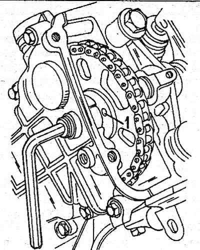
4.5 Position of the dowel pin (1) in the camshaft sprocket before removing the cylinder head

4.5 Position of the dowel pin (1) in the camshaft sprocket before removing the cylinder head


6. Fix the above mentioned special tool to the camshaft drive cover (see illustration). Lightly tighten the bolts and secure the crankshaft sprocket as shown using the bolt inserted into the sprocket hole and the nut.
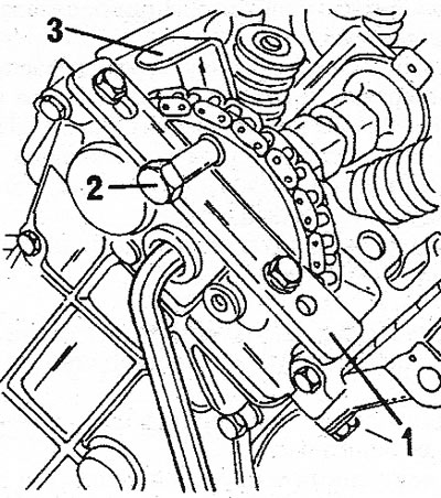
4.6 To install the camshaft sprocket, a special tool (1) is mounted in the camshaft drive cover.…

4.6 To install the camshaft sprocket, a special tool (1) is mounted in the camshaft drive cover. The bolt (2) and holder (3) prevent the sprocket from falling


7. Remove the cylinder head mounting bolts and rocker shaft as described earlier. Loosen the bolts in the opposite order to that shown in Illustration 3.146.

8. Unscrew the mounting bolt and remove the key from the camshaft groove.

9. Slowly loosen the sprocket mounting bolt until the camshaft is free from the bolt.

10. Drive the dowel pins into the cylinder block as shown in Illustration 2.51.

11. Remove the coolant hose and outlet pipe from the cylinder head and remove the four bolts securing the camshaft cover to the cylinder head.

12. Remove the cylinder head (hit it from the side with a rubber mallet). The liners should remain in the cylinders. Remove the cylinder head gasket.

13. If you need to remove the camshaft drive cover, insert a screwdriver into the end of both tensioners and turn to the right. Check the position of the installation mark as described earlier, since one of the shafts may turn. Connect all cables, wiring and install all parts.


14. Fill with coolant and connect the battery.

Petrol 4-cylinder engine


15. Drain the coolant from the cooling system.

16. Disconnect all electrical wiring. Disconnect the hoses from the water pump.

17. Remove the intake manifold with carburetor or injection system parts, exhaust manifold, engine guard, power steering pump drive belt one by one (if installed), water pump drive belt and steering gear housing cover. Remove all connections between the ignition distributor and the drive shaft and the vacuum hose.

18. Unscrew both bolts (see illustration) and press on the tensioner side of the drive belt. Remove the toothed drive belt from the pulleys.
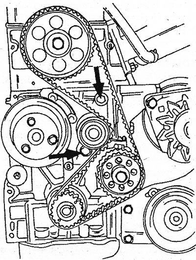
4.18 To remove the toothed drive belt, loosen both tension roller bolts and push the roller to the…

4.18 To remove the toothed drive belt, loosen both tension roller bolts and push the roller to the left


19. Remove the central connector socket for connecting the diagnostic equipment and the cylinder head cover.

20. The remaining work is carried out in accordance with the instructions in the engine description. To remove the cylinder head mounting bolts, refer to the drawings. Do not attempt to remove the cylinder head by pulling it upwards, as the cylinder liners may stick to the gasket and the seal on the lower surface of the cylinder liner will break. Before removing the head, move it to the side. Assembly of the cylinder head was described when assembling the engine.


Turbocharged diesel engine


21. Drain the coolant from the cooling system.

22. Disconnect all electrical wiring from the cylinder head.

23. Disconnect the hoses from the water pump, fuel lines, etc. The turbocharger must also be removed (disconnect the fuel lines, oil lines, unscrew the holder and two bolts).

24. Remove in the following order: air filter, intake pipe, exhaust manifold, shield under the engine, water pump belt and steering gear housing cover.

25. Remove the toothed drive belt as described in the relevant chapter for the diesel engine. A special device will be required to lock the crankshaft at TDC.

26. Remove the cylinder head cover bolts. Perform the remaining work as when disassembling the engine. To avoid damaging the seals on the lower part of the liners, do not remove the cylinder head upwards. Assemble as described for the engine.
This article is available on: russian, bulgarian, belarusian, ukrainian, serbian, croatian, romanian, polish, slovak, hungarian
Article has been reviewed by editor: Fedoseev Denis
Share with friends:
Previous
Espace I and II: Engine repair
Next

Engine — assembly
Engine — disassembly
Engine removal and installation — general description
Engine specifications
Cylinder head — disassembly
Cylinder head — assembly
Valve clearances — adjustment
Pre-chambers (diesel engine) — general description
Pistons and connecting rods — general description
Other articles on other Renault models

➽ Disassembly and assembly of the cylinder head, K7M engine (8… Renault Logan 2 (2012-2020)
➽ Cleaning the cylinder head of the K4M engine Renault Fluence 1 (2009-2020, petrol)
➽ Installing the cylinder head gasket (K4M engine) Renault Laguna 2 (2001-2007)
➽ Cleaning, inspection and maintenance of the cylinder head and… Renault Megane 1 (1995-2002)
➽ Engine cylinder head repair Renault Symbol 2 (2008-2013, petrol)
Link to this article in different formats
Reviews and comments of visitors
No comments yet


Add two numbers 21 + 36


Renault 19 (1988-1996) 
  • General information
  • Maintenance
  • Power unit
  • Engine repair
  • Exhaust system
  • Cooling system
  • Supply system
  • Single-point injection
  • Multi-point injection
  • Diesel injection system
  • Transmission
  • Clutch
  • Car gearbox
  • Chassis, running gear
  • Car suspension
  • Steering
  • Brake system
  • Wheels and tires
  • Body and interior
  • Exterior (external elements)
  • Interior (internal elements)
  • Heating and ventilation
  • Electrical equipment
  • Equipment and devices
  • Headlights and lighting
  • Ignition system
  • Power devices
  • Electrical circuits
Espace I and II (1984-1996) 
  • General information
  • Introduction to the guide
  • Troubleshooting
  • Power unit
  • Engine repair
  • Cooling system
  • Carburetor fuel system
  • Injection fuel system
  • Diesel fuel system
  • Ignition system
  • Transmission
  • Clutch
  • Car gearbox
  • Drive shafts
  • Chassis, running gear
  • Brake system
  • Steering
  • Front suspension
  • Rear suspension
  • Body and interior
  • Exterior (external elements)
  • Interior (internal elements)
  • Doors, locks and windows
  • Electrical equipment
  • Equipment and devices
  • Electrical circuits
Espace III (1996-2002) 
  • General information
  • Introduction to the manual
  • User manual
  • Power unit
  • Petrol engines F3R
  • Petrol engines Z7X
  • Diesel engines G8T
  • Diesel engines G9T
  • Transmission
  • Clutch
  • Mechanical gearbox
  • Automatic gearbox
  • Drive shafts
  • Chassis, running gear
  • Steering
  • Front suspension
  • Rear suspension
  • Brake system
  • Body and interior
  • Exterior (external elements)
  • Interior (internal elements)
  • Doors, locks and windows
  • Heating and ventilation
  • Electrical equipment
  • Equipment and instruments
  • Power devices
  • Electrical circuits
RenaultBook.ru © 2018–2026 | Mobile version | News and articles | Sitemap: EN BG BY UA RS HR RO PL SK HU | Administration | Site search | Bookmark
Duster 1 (2009-2017) | Fluence 1 (2009-2020, petrol) | Kangoo 1 (1997-2007) | Laguna 2 (2001-2007) | Logan 1 (2004-2012, petrol) | Logan 2 (2012-2020) | Megane 1 (1995-2002) | Megan 2 (2002-2009, petrol) | Sandero 1 (2007-2012, petrol) | Scenic 1 (1996-2003) | Symbol 1 (1999-2008, petrol) | Symbol 2 (2008-2013, petrol) | Renault 19 (1988-1996) | Espace I and II (1984-1996) | Espace III (1996-2002) | Clio 1 (1990-1998) |
We want your visit to be comfortable 😌 and use cookies 🍪 to do so.