
Rocker mechanism - all engines
1. Check the rocker shaft for scratches or excessive wear and replace if necessary. Lubricate all parts liberally and install on the rocker shaft in the assembly sequence, in case) the same parts will be installed.
2. On a gasoline engine, put the #5 pivot bracket onto the rocker shaft and rotate the shaft so that the oil holes are on the bottom surface. Attach the pivot bracket with the new safety pin to the axle. When assembling the axle, follow illustration 5.8.
3. Turbo diesel engine (see illustration 5.26) put on the hinge bracket «E» onto the rocker shaft and rotate the shaft so that the lubrication holes are on the bottom surface. Attach the pivot bracket to the axle with the bolt. Then install in the following order: inlet rocker, spring, exhaust rocker, next hinge bracket with projection towards flywheel, and then install all remaining parts in the same order. Insert new filter (2) into the axis (1) and close the cap (3) tightening force 20 Nm.
4. For V6 engines, lubricate all parts and fit onto the axle one by one. If the same parts are installed, be careful about their marking. Ensure that the valve actuator clearance adjustment bolts are on the prescribed side and do not mix up the spacers. The strongest spacer is closer to the end of the rocker shaft.
Valves
5. Clean the valves, preferably with a wire brush. Inspect the valve surface for scale, gouges, or other signs of wear. If the wear is negligible, you can grind the chamfer of the valve. Remove only a minimal layer of metal, leaving enough material in the form of a clearly defined cylindrical belt.
6. Measure the diameter of the valve stem and with it the bore diameter of the guide bushing. If these values exceed the allowable values, replace the rod and bushing.
Valve seats
7. Valve seats can be cut to original angles. If these works are done carefully, there is no need to grind the valves. Finish the seat surface with a grinding tool. After grinding, check the concentricity of the valve seat face to the stem guide. The left shows the correct seating of the valve in the seat (see illustration). Turbocharged diesel engine
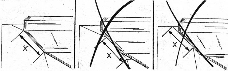
6.7 The right position of the valve in the seat is shown on the left. Both other options are wrong position
8. The following measurement is taken after the valve seat has been machined:
A) Insert the valves in order into the well-machined seats and press firmly.
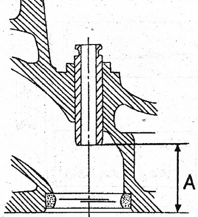
b) Measure with a dial micrometer or feeler gauge the distance from the top of the valve head to the surface of the cylinder head (see illustration). The valve head surfaces must sink at least 0.8-1.15 mm into the head surface. This value is very important, because otherwise the valves will hit the pistons. Replace the cylinder head if necessary.
6.8 Measuring the installation height of the valves. The valve surfaces must sink into the surfaces of the cylinder head.
Valve springs
9. To check the valve springs, use a special device. If you do not have such a device, compare the used spring with a new one. To do this, insert both springs into a vise and slowly compress them. If both springs are compressed equally, they have approximately the same elasticity. If the old spring compresses more than the new one, replace it.
10. Install the springs one by one on a smooth surface with their closed parts at the bottom. Install a steel corner next to the spring. Measure the gap between the spring and the angle at the top, it should be no more than about 2.0 mm. Otherwise, the spring is exhausted.
Valve guides
11. Wipe the bushings with a rag soaked in gasoline. The inner surface of the sleeve is best cleaned by installing a wire brush in a drill.
12. Use a small punch to check the valve guides for wear. If the punch goes into the hole, the sleeve must be replaced. If there is no punch of a suitable diameter, you can use a valve. To do this, insert the valve into the sleeve. Measure the clearance between the valve and the sleeve. Although no specific value has been established, it is generally accepted that the gap can be no more than 1.0-2.0 mm. The outer diameter of the repair sleeve is increased (marked with one or two grooves on the outside, see specifications) therefore, in order to insert a new bushing, it is necessary to ream the hole in the cylinder head. Measure the amount of protrusion of the bushing above the platform for the spring plate to drive the new bushing in by the same amount. Determination of the installation size for different engines is made in accordance with the illustrations. It is very important to measure the places indicated by the arrows.
13. For a V6 engine, measure the distance between the chamfer of the guide sleeve and the valve seat (see illustration). At the intake valve (A) it should be 30 mm, at the exhaust valve (IN) - 26 mm. New valve guides are pressed in to the specified dimensions.
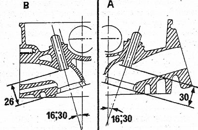
6.13 Section of the cylinder head of the V6 engine. Mounting sleeves must be pressed in to the set value A Inlet valve B Exhaust valve
14. The stepped ends of the guide bushings should point in the direction shown in the figure, i.e. to the top of the cylinder head.
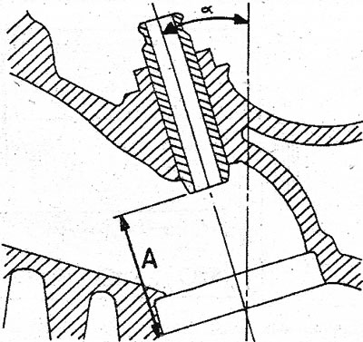
15. For a turbocharged diesel engine, measure the clearance between the inner chamfers of the valve guides and the surface of the cylinder head (see illustration). All bushings should have a clearance of 32.5 mm. The stepped end of the sleeve must be turned towards the valve seat.
6.15 Sectional view of the cylinder head of a turbocharged diesel engine. Gap «A» installation of guide bushings corresponds to 32.5 mm
16. For a gasoline 4-cylinder engine, the clearance is measured in accordance with the illustration. The clearance of the bushing for the intake valve is 33.20 mm, for the intake valve it is 32.00 mm. The stepped ends of the guide bushings must face the valve seats.
6.16 Section of the cylinder head of a gasoline 4-cylinder engine. Gap «A» achieved as described in the text
17. The guide bushings on the V6 engine and on the gasoline 4-cylinder engine are set at an angle, i.e. the cylinder head must be rotated appropriately to fit the guide bushings vertically. When pressing the guide bushings, constantly measure the clearance. After installation, ream the hole in the pressed bushing to a diameter of 8 mm. This provides the prescribed clearance for the valve stems. The valves are installed in the reverse order of removal. Pay attention to the following points:
18. Lubricate all parts of the valves well.
19. Install the valve springs with the flat surface of the helix towards the cylinder head.
20. Intake and exhaust valve cotters are the same, but must be installed on the same valves if they are to be installed again.
21. Fit the support washer and springs onto the valve guide. Install the spring cap and compress the valve with a puller until the valve cotters can be inserted into the groove in the stem (pliers). After installing the valve crackers, tap the valve bevel with a rubber mallet. If the cotters are not installed correctly, the spring plate, springs, etc. fly out. For this reason, cover the valve with a cloth beforehand.
22. Install the camshafts. Do not interchange the two shafts on the V6 engine. On a four-cylinder engine, correctly install the key into the camshaft groove.
23. Further assemble the cylinder head in accordance with the instructions for assembling the engine. The installation of the toothed drive belt will be described below.
Cylinder head gaskets
24. Remember that both seals on a V6 engine are different. Only the correct gasket is always fitted to the corresponding head. The gasket thickness of a turbocharged diesel engine must be set as described previously. When choosing a gasket for a gasoline 4-cylinder engine, its volume is taken into account.