
Petrol 4-cylinder engines
1. Install the mounting bracket into the exhaust manifold screw hole on the cylinder head.
2. Remove the spark plugs, distributor, ignition, top water hose, and everything else mounted on the part head.
3. Block the camshaft pulley and loosen the pulley bolt.
4. Remove the rocker shaft, camshaft and engine mounting lugs.
5. Use a special puller to remove the valves. Install it on the head and compress the springs until the valve cotters come out, which are removed with pliers (see illustration). Remove the valve puller and remove the valve disc, springs and spring washer in turn. All parts of one set must be numbered and put in a separate box or bag.
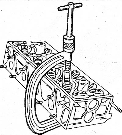
5.5 Removing the valves with a special puller
6. Remove the valves one by one from the guide bushings and lay them out in a sequence convenient for assembly.
7. If you do not have a special puller, use a piece of tubing. Place the tube on the valve spring seat and strike the tube to compress the spring. Valve crackers get into the inside of the tube. After that, you can remove the rest of the details.
8. The axis of the rocker arms is equipped with a filter («1» in the illustration), which must always be changed when disassembling the shaft. Before removing the rocker shaft, install the safety pin (2) from hard material. Now start disassembly. To remove the rocker shaft, unscrew the plug (1) from the end of the shaft. Pull out the safety pin (2), remove the rest of the parts from the shaft in turn and mark each of them in turn. Keep the following points in mind when assembling:
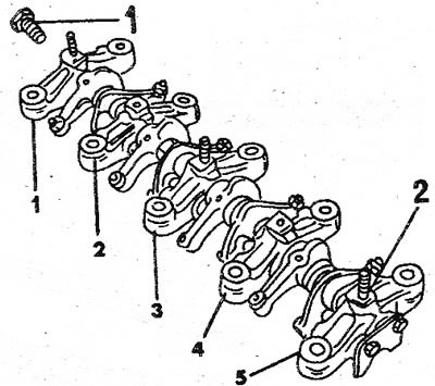
5.8 Rocker arm assembly. Pin (2) holds the shaft in the #5 articulated bracket. Under the plug (1) there is a filter
9. Rocker axle posts #1, #2, #3, and #4 are the same but still need to be numbered if they are to be installed again. The rocker arms have an oil hole (1, see illustration) for camshaft lubrication, screw hole (2) for cylinder head cover stud (only for swivel brackets 1 and 3) and a tab for adjustment. It should be turned towards the star.
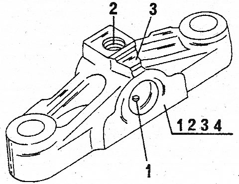
5.9 Rocker arm swivel bracket with mounting location for bearings No. 1, 2, 3 and 4
10. Bearing #5 has two extra screw holes (1, see illustration) for fixing the camshaft key (for adjusting the axial clearance) and 3 mm pin (2) to hold the rocker mechanism.
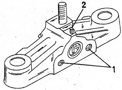
5.10 Swivel brackets 1,2, 3 and 4 for rocker shaft
11. All done thoroughly clean.
Petrol 6-cylinder engine (V6)
12. Turn out the spark plugs, remove the camshaft key, unscrew the coolant outlet plug, remove the mounting lugs and all other parts installed on the head. Lastly, remove the alternator mount on the left cylinder head.
13. Remove the valves as previously described (see illustrations 3.7b and 5.5). Mark all valve parts for installation. Disassembled valves are shown in the illustration.
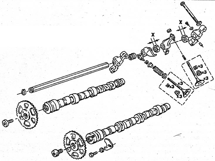
5.13 Camshafts, rocker shaft and valves on a V6 engine. Spacers «X» differ in thickness
14. To remove the rocker axle, unscrew the bolts from the pivot brackets and remove the individual parts from the shaft. Mark the details in the order they were taken. When assembling, follow illustration 5.13 and observe the following points:
15. Left and right shaft are not the same. They are suitable only for the block head corresponding to them.
16. The rocker shaft must be installed with the lubrication holes down.
17. The thickness of the spacer washers is different. Watch where they are installed.
18. The rocker arms have bolts for adjusting the clearance in the valve actuator either on the left side or on the right side. The lever must be marked accordingly before disassembly.
19. The rocker swivel bracket has a flat bead on the side. This side must face out, i.e. point towards the circlip at the end of the axle.
20. After disassembly, clean all parts thoroughly and check as described below.
Diesel engine
21. Disconnecting the cable from the glow plugs, disconnect the fuel outlet line and remove the injectors together with the sealing washers from the cylinder head
firewood. Remove the fireproof washers installed between the nozzles and the cylinder head. Remember how they were installed (see illustration).
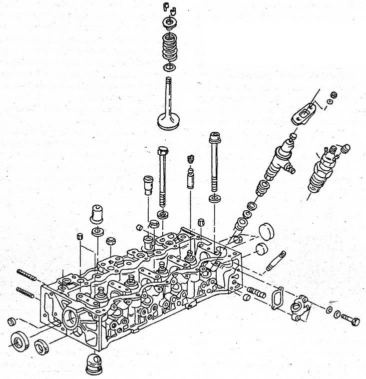
5.21 Cylinder head components - turbocharged diesel engine
22. Remove glow plugs.
23. Properly block the camshaft sprocket and remove the bolt from its middle.
24. If necessary, knock out the pre-chambers from the cylinder head. To do this, insert a small punch into the nozzle hole and knock out the prechamber.
25. Remove the rocker shaft, camshaft, mounting eyes and thermostat housing.
26. Valves remove in the same way as it was described for the petrol 4-cylinder engine. Valve puller also suitable for diesel engines (see illustration 5.5). There is an oil filter on the rocker axle, which must be replaced when the axle is removed. The rocker arm assembly is shown in the illustration. When disassembling the axle, remove the plug (3) from the end of the axle and remove the filter. Remove the parts one by one from the axis, marking them along the way. Pay attention to the following points:
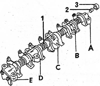
5.26 Rocker shaft assembly - turbocharged diesel engine. Alphabetic and numeric designations are indicated in the text
27. Rocker arm pivot brackets A, B, C, and D are similar and must be marked for later installation. They have oil holes (2, see illustration) to the camshaft bearing lubrication channel and replaceable elements (1) And (3); the last one is on the flywheel side.
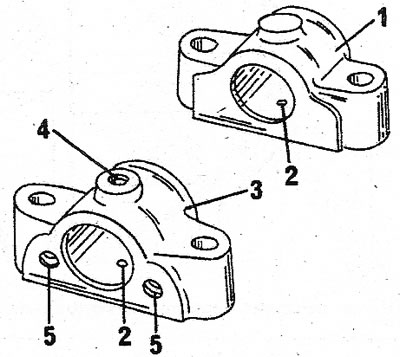
5.27 Swivel brackets of the rocker shaft. Numerical designations are indicated in the text
28. Swivel bracket «E» has two additional threaded holes (5, see illustration 5.27) for fastening the camshaft plate (it regulates the axial clearance) and threaded hole (4) for fixing the axis of the rocker arms. The lubrication holes of the rocker shaft must point towards the camshaft.
29. Intake and exhaust rocker arms are the same and should be properly marked. All rocker arms have a channel in the lower surface for camshaft cam lubrication. Clean all parts and inspect them carefully.