
V6 engine
2. In the following, the inlet valve will be denoted by the letter «E», and graduation letter «A».
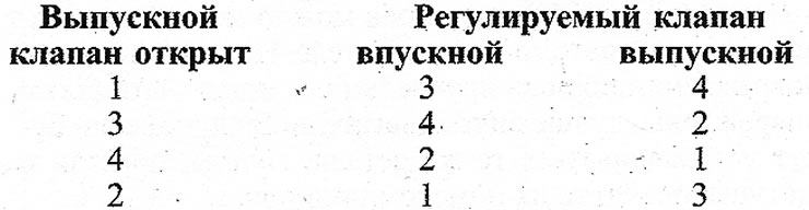
3. To adjust the valves of the left cylinder head (see illustration):
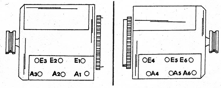
7.3 Inlet valve position (E) and exhaust valves (A) on both cylinder heads. The countdown is from the engine pulley
A) Turn the crankshaft until the valves of the first cylinder move, i.e. one valve closes and the other opens. Valves can be adjusted in this position of the engine «E3» and «A2».
b) Turn the crankshaft until the valves of the second cylinder move and adjust the valves «E1» and «AZ».
With) Turn the crankshaft until the valves of the third cylinder move and adjust the valves «E2» and «A1».
4. Now adjust the valve clearances of the right cylinder head as follows (see illustration 7.3):
A) Turn the crankshaft until the valves of the fourth cylinder move and adjust the valves «E6» and «A5».
b) Turn the crankshaft until the valves of the fifth cylinder move and adjust the valves «E4» and «Ab».
With) Turn the crankshaft until the valves of the sixth cylinder move and adjust the valves «E5» and «A4».
5. To keep the engine running, jack up one of the front wheels and shift into 5th gear. Thus, by rotating the wheel, you can set the piston to the desired position. To make turning easier, remove the spark plugs. Valve clearance - measured with a feeler gauge of appropriate thickness, i.e. 0.10 or 0.25 mm inserted between the chamfer of the valve stem and rocker arm. The dipstick must have a smooth tip.
6. Use a screwdriver and ring wrench to make adjustments. When tightening, block the bolt with a lock nut so that the adjustment results do not change. It should also be mentioned that there is a special tool for adjusting the valve clearance. He holds the tension bolt while the lock nut is removed (see illustration).
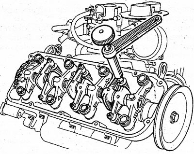
7.6 Valve clearance adjuster on V6 engine
7. There is a second method for adjusting the valve clearance:
A) Set the piston of the first cylinder to TDC. This can be achieved by moving the rocker arms. Both rocker arms should have a small gap. The valves of the fifth cylinder must move.
b) In this position of the engine, adjust the following valves in accordance with illustration 7.3: «E1», «E2», «E4» (intake valves) and «A 1», «AZ» and «A6» (exhaust valves).
With) Rotate the engine half a turn. Now the valves of the fifth cylinder are closed, and the valves of the first cylinder have switched.
d) In this position of the engine, the following valves are regulated: «E3», «E5» and «E6» (intake valves), and «A2», «A4» and «A5» (exhaust valves).
Adjustment on 4-cylinder engines
8. Although the valve adjustment process for all engines is identical, there are some differences between individual engines, since the TDC setting mark for some engines is on the outside of the camshaft drive cover, while for others it is on the inside of the steering gear case. z
Petrol 4-cylinder engines (except JTT and J7R)
9. First of all, find the TDC setting mark. On some engines that do not belong to the mentioned group (see right illustration) there is a camshaft alignment mark. If this happens, adjust the valves as described for engines «Fri» and «J7R».
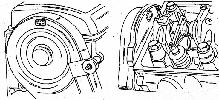
7.9 Left - mark on the outside of the camshaft drive cover. Right - mark for individual cylinders
10. Turn the crankshaft until the valves of the first cylinder are at TDC. Remove the cylinder head cover and check that the valves of the fourth cylinder have moved. To keep the engine running, jack up the front wheel and engage fifth gear. Turn the wheel until you get the correct setting. The spark plugs can be turned out to facilitate rotation.
11. In this position, adjust the intake valve of the third cylinder and the exhaust valve of the fourth cylinder. Both of these valves are closed.
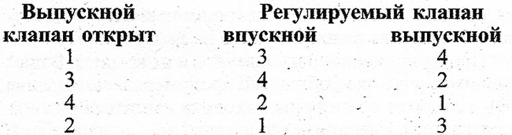
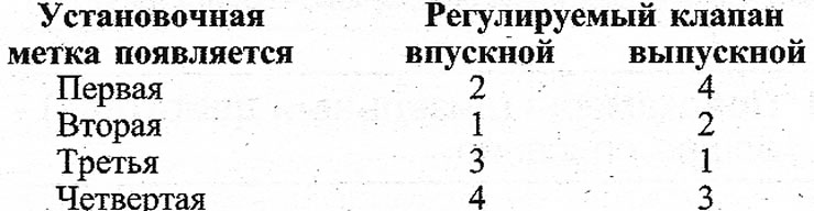
12. Rotate the engine again until the next exhaust valve opens and adjust according to the following table:
13. The valves can also be adjusted by turning the engine until both valves of the first cylinder are closed, i.e. both rocker arms should have a slight gap. Adjust the intake and exhaust valves of that cylinder and rotate the engine to open the next pair of valves. Valves close in firing order and if this is remembered, closed valves can be easily found.
14. Measure the valve clearance. To do this, insert a measuring probe of the appropriate thickness (see specifications) between the valve stem and rocker arm. The measuring probe must have a smooth tip.
J7R and J7T engines
15. Turn the crankshaft until the piston of the first cylinder is at TDC. The valves must move. The TDC mark of the first cylinder is located on the outside of the camshaft drive cover, as shown in illustration 7.9 on the left.
16. Turn the engine so that the first alignment mark on the camshaft pulley, on the inside, is in line with «ledge» in the pulley cover.
17. In this position, adjust the intake valve of the second cylinder and the exhaust valve of the fourth cylinder.
18. Rotate the crankshaft again to the next alignment mark on the inside of the pulley cover. Installation order:
19. You can also adjust the valves as follows. Turn the engine so that both valves of the first cylinder are closed, i.e. both rocker arms had a small gap. Adjust the intake and exhaust valves of that cylinder and rotate the engine to open the next pair of valves. The valves close in firing order and if you remember this, closed valves can be easily found. Exhaust and intake valves, when viewed from the drive end, are arranged in this sequence: intake-exhaust-intake-exhaust, etc.
20. Valve clearance is measured as described earlier.
Turbocharged diesel engine
21. Adjusting the valves of a turbodiesel engine is carried out in the same way as described for gasoline 4-cylinder engines (except J7R and J7T).
22. Glow plugs or injectors can be removed from a diesel engine to allow the engine to spin more easily. Position of individual valves (see illustration).
7.22 Position of inlet valves (A) and exhaust valves (IN) on a diesel engine. On a 4-cylinder petrol engine, they are located in the same way