



Disassembly procedure:
- remove the cylinder head and place it on a workbench with a wooden surface;
- remove fuel injectors;
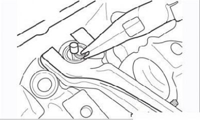
Figure 3.29. Compressing the valve spring and removing the crackers
- using a special device, compress each valve spring and, having moved the upper spring plate a sufficient distance down the valve stem, remove the crackers (Figure 3.29). If the crackers are "stuck", carefully tap the end of the valve with a hammer with a copper striker;
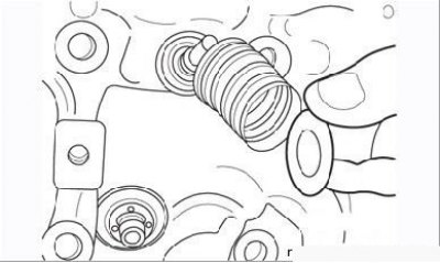
Figure 3.30. Removing the upper valve plate and spring
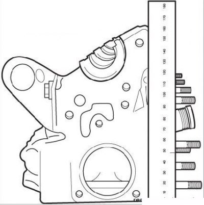
Figure 3.32. Set of parts for installing the valve in the package
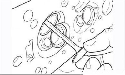
Figure 3.31. Removing the valve from the guide bushing
- remove the top plate, spring and take the valve out of the guide bushing (Figure 3.30, 3.31). Place the set of parts in a separate plastic bag, marking the location of their installation (Figure 3.32);
[The original can be found on the website: renaultbook.ru]
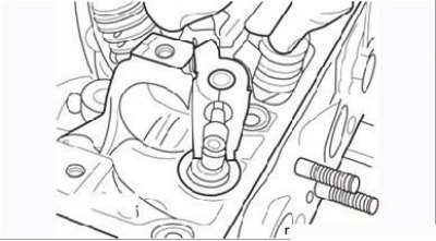
Figure 3.33. Removing the oil seal
- remove the oil scraper caps, which also serve as the lower spring plates, from all guide bushings (Figure 3.33).
Inspection of parts
Carefully clean the removed parts from dirt and carbon deposits. Remove the remains of the old gasket on the mating surface of the cylinder head only by chemical means (see subsection "Removal and installation the cylinder head"). Use only aluminum scrapers to remove carbon deposits from the combustion chambers. Thoroughly wash the cylinder head with kerosene or white spirit. Use a wire brush clamped in a drill chuck to remove carbon deposits from the valves.
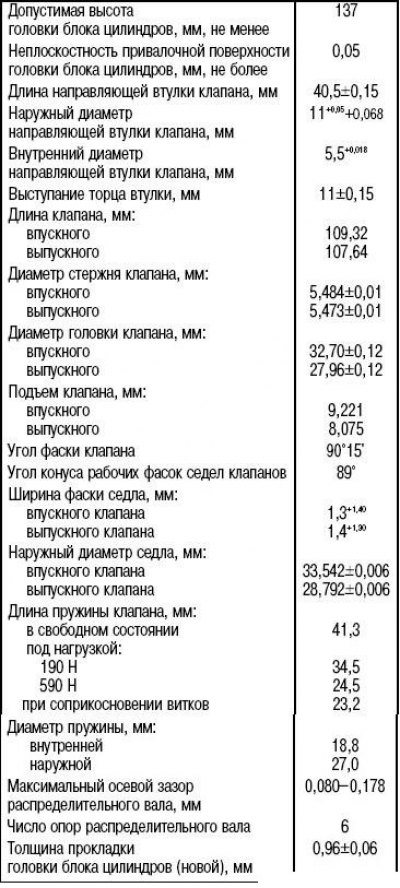
When inspecting and measuring parts, take into account the technical data given in Table 3.2.
Carefully inspect the cylinder head for cracks. If cracks are found, the head must be replaced.
Check whether the flatness of the head mating surface is damaged using a metal ruler, applying it lengthwise, crosswise and diagonally and measuring the gap using a feeler gauge. The permissible gap in all dimensions is no more than 0.05 mm. If the gap exceeds 0.05 mm, the head should be replaced.
Inspect the valve faces for pits and burns, paying particular attention to the exhaust valves. If significant damage is found on the facets, replace the valve. Minor surface defects are eliminated by grinding the valve.
The valve is lapped as follows. Apply a small amount of coarse abrasive paste to the contact surface of the valve or seat and insert the valve into the guide sleeve. Mount the valve lapping device with a suction cup on the valve plate and lap the valve using semi-rotary movements. From time to time, change the position of the valve relative to the seat and continue lapping until the surfaces of the seat and valve acquire a uniform gray color. Then repeat the lapping using a fine paste. After finishing the lapping, remove the remains of the lapping paste, making sure that the paste does not get into the guide sleeve. Wipe the valve and seat with a rag soaked in kerosene, and then with a dry rag.
Make sure that the valve stem is not bent by rotating it. There should be no chips or signs of wear on the end of the valve. Replace damaged valves.
Measure the valve stem diameter using a micrometer and compare the measurement results with the data in Table 3.2.
Measure also the inner diameter of the corresponding guide bush. Calculate the clearance and compare the result with the data in the mentioned table. If the clearance is outside the permissible limits, replace the guide bush or valve. It is better to entrust the replacement of bushes to specialists. If you do the repair yourself, use a mandrel with shoulders and knock out the guide bush in the direction of the combustion chamber. Place the new bush in the freezer for one hour before installation, then use a mandrel to press it from the camshaft side into the head to the prescribed height of protrusion above the surface. Ream the inner diameter of the guide bush to the required size.
Check the valve seats. If there is significant damage to the surface, the seat chamfers must be ground on a special machine. Minor surface defects can be removed by lapping, as described above. If it is necessary to grind the valve seats, the maximum possible grinding depth should be specified, since excessive metal removal will not ensure proper operation of the hydraulic valve tappet. This issue should be left to specialists.
Inspect the valve springs - they should not have broken or cracked coils. The spring dimensions should correspond to the data given in Table 3.2. The geometric shape of the spring should not be changed. Replace damaged springs.
Table 3.2. Technical data of the cylinder head, valve train components and camshafts
Inspect the hydraulic tappets for wear and cracks. Minor abrasions on the working surface are acceptable.
All oil seals must be replaced without fail.
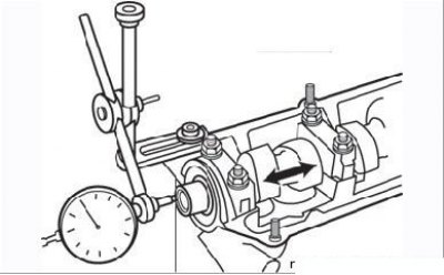
Figure 3.34. Measuring the axial clearance of the camshaft
Check the axial clearance of the camshafts using an indicator (Figure 3.34) and compare the result with the table.
Inspect the camshafts. The surface of the journals and cams should be smooth with a matte shine.
A bluish color of the surfaces indicates engine overheating or insufficient lubrication, while scuffs, chipping, and bright shine indicate wear. Accelerated wear begins immediately after damage to the outer layer of the camshaft, so damaged parts should always be replaced.
On a special stand, check the camshafts for radial runout. Its maximum permissible value is not specified by the manufacturer, but a value of 0.1 mm can be used as a guide. If the measurement result exceeds this value, then the issue of replacing the camshaft should be decided.
Assembly order:
- lubricate the valve stems with engine oil and insert them into the cylinder head guide bushings;
- place the installation tip supplied with the valve stem seals onto the valve stem. Do not oil the valve stem seals before installation;
- holding the valve pressed against the seat, carefully place the oil scraper cap onto the tip without tilting it;
- push the cap down the rod to the guide bushing and remove the tip;
- make sure the cap is installed straight and install the pusher to press it in;
- tap the top of the tappet with your palm and move the cap until it touches the cylinder head;
- install the spring and the upper spring plate;
- using the tool, compress the spring and install the crackers into the groove on the valve stem. To facilitate assembly, lightly lubricate the crackers with consistent grease;
- assemble the remaining valve assemblies in the same manner;
- using a wooden spacer, tap lightly on the protruding ends of the valves to ensure the parts are seated correctly;
- install fuel injectors.